AK-270 Ver la hoja de datos (PDF) - Unspecified
Número de pieza
componentes Descripción
Lista de partido
AK-270 Datasheet PDF : 13 Pages
| |||
b) The soldering iron temperature depends on the type of solder used.
If you are using a typical 60/40 lead solder, the temperature should be set
depending on the thickness anywhere between 370 to 500 °F (187 to 260 °C). If
you are using a lead-free solder, increase above temperatures by 40 to 70 °F (5
to 20 °C).
*ATTENTION* HIGHER TEMPERATURES WILL DAMAGE THE COMPONENTS
ALONG WITH THE CIRCUIT BOARD.
*ATTENTION* DO NOT TOUCH THE SOLDERING IRON TIP WHEN IT IS HOT.
c) It is recommended that you clean the board with a brush, isopropyl alcohol and
lint-free cloth to get rid of any residue, glue or dirt. This way the solder will
create a better joint with the copper pads.
d) Have your flush cutter, needle nose plier or tweezers handy.
e) Having a roll of paper tape helps you to keep the components in place when
soldering on the bottom side of the board. *ONLY FOR THROUGH-HOLE
COMPONENTS*
f) Have a rosin flux pen or paste handy. Adding flux to the pads before soldering
the component makes the process easier by letting the melted solder to flow
better on the pad and create a better joint.
*ATTENTION* SOLDERING SHOULD BE DONE IN A VENTILATED AREA.
BREATHING SOLDER FUMES WILL HARM YOU.
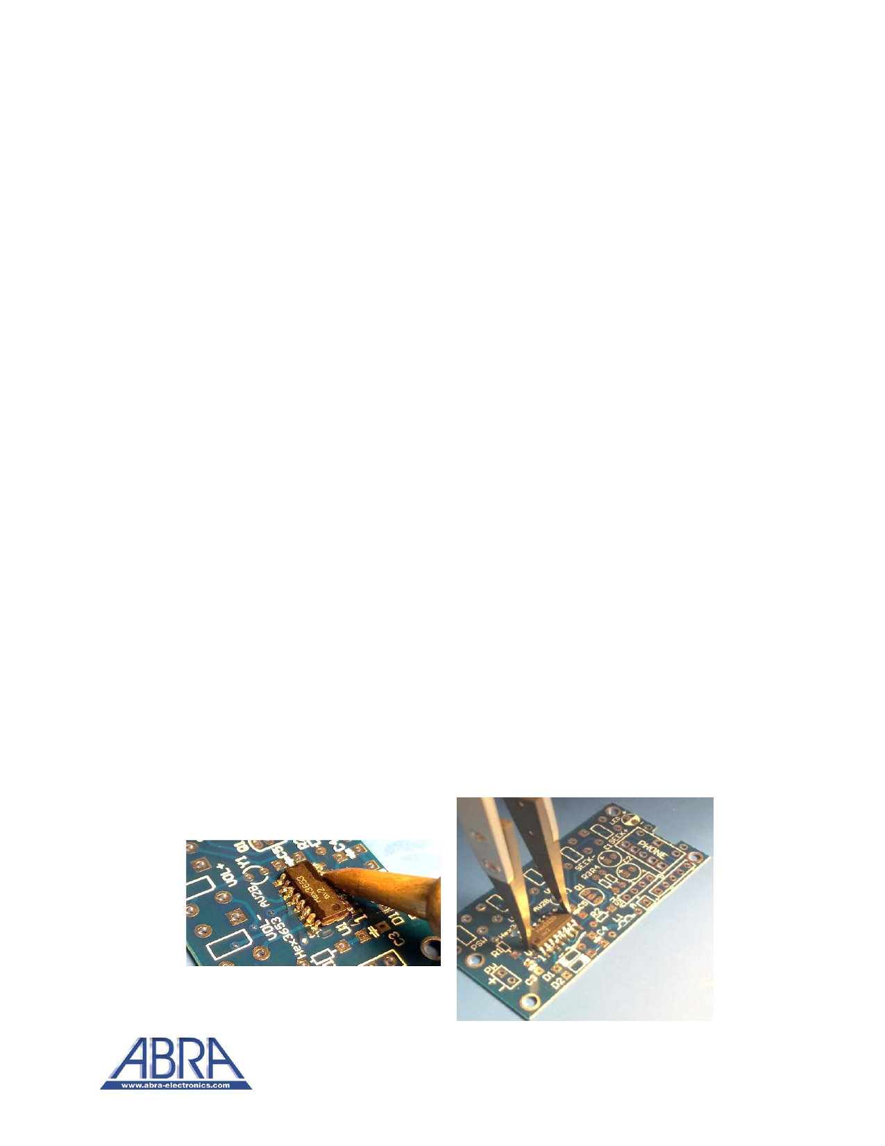
6) Start the assembly by soldering the SMD HEX3653 chip (U1). Depending on your level of
comfort and skills, you can add an appropriate amount of solder to all sixteen pads then
place the chip on the board and heat up the pins onto the previously added solder until
the IC chip leads and the solder fuse together.
Otherwise, add some solder to the pads on one side of the chip, place the chip on the
board and heat up the pins onto the solder. Once the chip is secured, solder the rest of
the pins on the opposite side using your flat head tip. Remember to use your set of pliers
or tweezers to place an SMD component in its designated location on the PCB.
10
Share Link: 