AD2S1200 Ver la hoja de datos (PDF) - Analog Devices
Número de pieza
componentes Descripción
Lista de partido
AD2S1200 Datasheet PDF : 24 Pages
| |||
AD2S1200
RESOLVER FORMAT SIGNALS
Vr = Vp × Sin(ϖt)
R1
S2
Va = Vs × Sin(ϖt) × Cos(θ)
R1
θ
S4
R2
R2
S1
S3
Vb = Vs × Sin(ϖt) × Sin(θ)
Vr = Vp × Sin(ϖt)
θ
S2
Va = Vs × Sin(ϖt) × Cos(θ)
S4
S1
S3
Vb = Vs × Sin(ϖt) × Sin(θ)
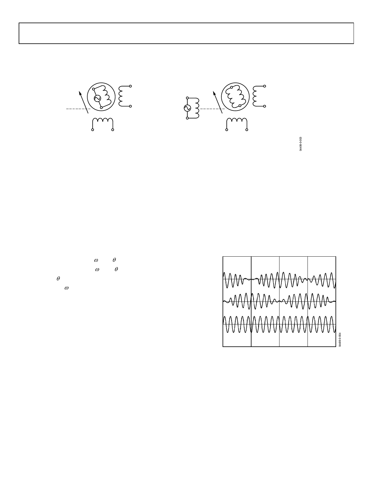
(A) CLASSICAL RESOLVER
(B) VARIABLE RELUCTANCE RESOLVER
Figure 3. Classical Resolver vs. Variable Reluctance Resolver
A resolver is a rotating transformer typically with a primary
winding on the rotor and two secondary windings on the stator.
In the case of a variable reluctance resolver, there are no wind-
ings on the rotor as shown in Figure 3. The primary winding is
on the stator as well as the secondary windings, but the saliency
in the rotor design provides the sinusoidal variation in the
secondary coupling with the angular position. Either way, the
resolver output voltages (S3–S1, S2–S4) will have the same
equations as shown in Equation 1.
S3 − S1 = E0 Sinωt × Sinθ
S2 − S4 = E0 Sinωt ×Cosθ
θ = Shaft Angle
Sinωt = Rotor Excitation Frequency
E0 = Rotor Excitation Amplitude
Equation 1.
The stator windings are displaced mechanically by 90° (see
Figure 3). The primary winding is excited with an ac reference.
The amplitude of subsequent coupling onto the stator secon-
dary windings is a function of the position of the rotor (shaft)
relative to the stator. The resolver, therefore, produces two
output voltages (S3–S1, S2–S4) modulated by the SinE and
CoSinE of shaft angle. Resolver format signals refer to the
signals derived from the output of a resolver as shown in
Equation 1. Figure 4 illustrates the output format.
S2 TO S4
(Cos)
S3 TO S1
(Sin)
R2 TO R4
(REF)
0°
90°
180°
270°
360°
θ
Figure 4. Electrical Resolver Representation
Rev. 0 | Page 8 of 24
Share Link: 