BD9483F Ver la hoja de datos (PDF) - ROHM Semiconductor
Número de pieza
componentes Descripción
Lista de partido
BD9483F Datasheet PDF : 32 Pages
| |||
BD9483F,FV
Datasheet
●3.5.4 MOSFET selection
Though there is no problem if the absolute maximum rating is larger than the rated current of the inductor L, or is
larger than the sum of the tolerance voltage of COUT and the rectifying diode VF. The product with small gate
capacitance (injected charge) needs to be selected to achieve high-speed switching.
* One with over current protection setting or higher is recommended.
* The selection of one with small on resistance results in high efficiency.
●3.5.5 Rectifying diode selection
A schottky barrier diode which has current ability higher than the rated current of L, the reverse voltage larger than the
tolerance voltage of COUT, and the low forward voltage VF especially needs to be selected.
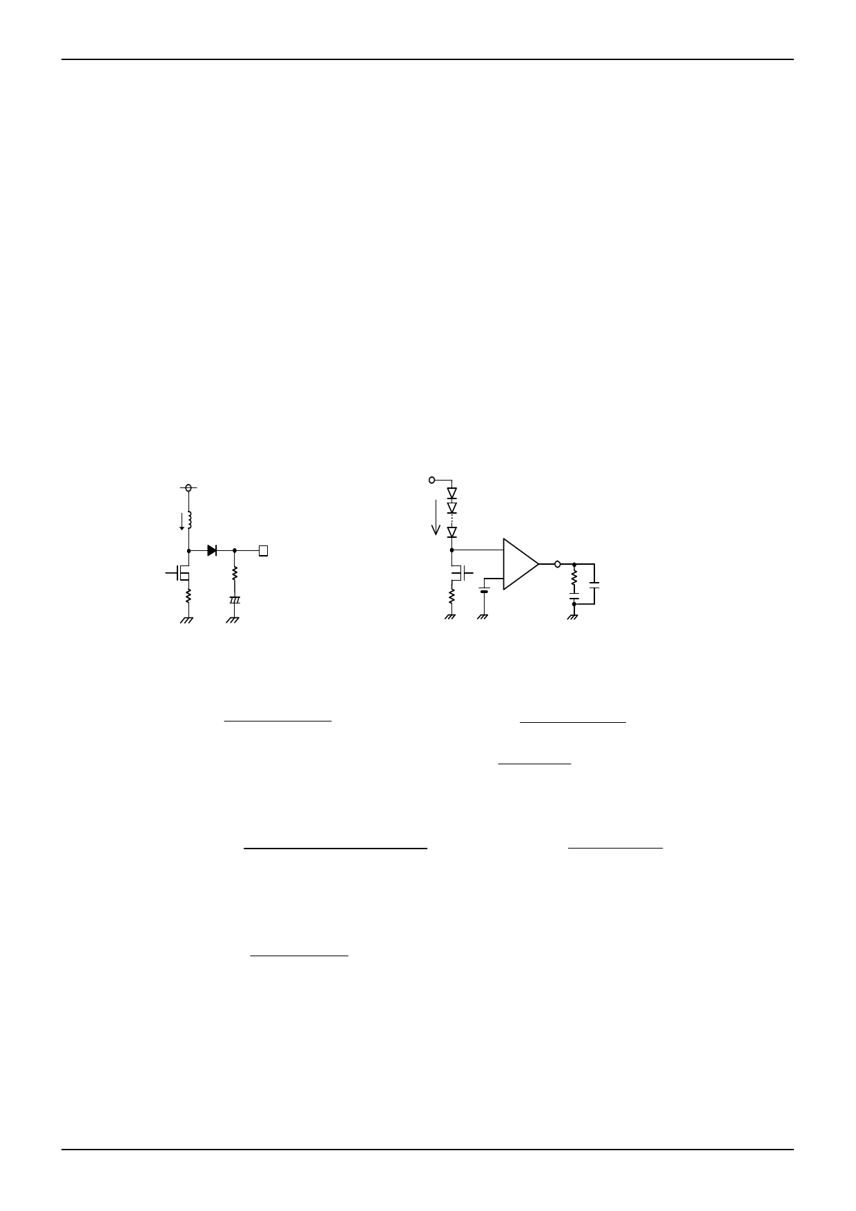
●3.6 Loop compensation
A current mode DCDC converter has each one pole (phase lag) fp due to CR filter composed of the output capacitor
and the output resistance (= LED current) and zero (phase lead) fZ by the output capacitor and the ESR of the
capacitor.
Moreover, a step-up DCDC converter has RHP zero (right-half plane zero point) fZRHP which is unique with the boost
converter. This zero may cause the unstable feedback. To avoid this by RHP zero, the loop compensation that the
cross-over frequency fc set as following, is suggested.
fc = fZRHP /5 (fZRHP: RHP zero frequency)
Considering the response speed, the below calculated constant is not always optimized completely. It needs to be
adequately verified with an actual device.
VIN
VOUT
L
VOUT
RESR
RCS
COUT
ILED
-
FB
gm
+
RFB1
CFB2
CFB1
Figure 31.
The output voltage block
Figure 32.
The error amp block
i.
Calculate the pole frequency fp and the RHP zero frequency fZRHP of DC/DC converter
f
p
I
LED
2π V C
[Hz]
OUT
OUT
Where ILED = the summation of LED current,
f ZRHP
VOUT (1
2π L
D VOUT VIN
D)2 [Hz]
I LED
(Continuous
Current
Mode)
VOUT
ii.
Calculate the phase compensation of the error amp output (fc = fZRHP/5)
R
FB1
5
f RHZP R CS
f p gm VOUT
I LED
(1
D)
[Ω]
Where gm 4.0 104[S ]
C FB1
1
2π R FB1 f p
[F]
iii.
Calculate zero to compensate ESR (RESR) of COUT (electrolytic capacitor)
C FB2
R ESR C OUT
R FB1
[F]
*When a ceramic capacitor (with RESR of the order of milliohm) is used to COUT, the operation is stabilized by
insertion of CFB2.
To improve the transient response, RFB1 need to be increase, CFB1 need to be decrease. It needs to be adequately verified
with an actual device in consideration of vary from parts to parts since phase margin is decreased.
www.rohm.com
© 2012 ROHM Co., Ltd. All rights reserved.
TSZ22111・15・001
19/29
TSZ02201-0F1F0C100100-1-2
28.Nov.2013 Rev.003
Share Link: 