RTL8201BL Ver la hoja de datos (PDF) - Realtek Semiconductor
Número de pieza
componentes Descripción
Lista de partido
RTL8201BL Datasheet PDF : 29 Pages
| |||
RTL8201BL
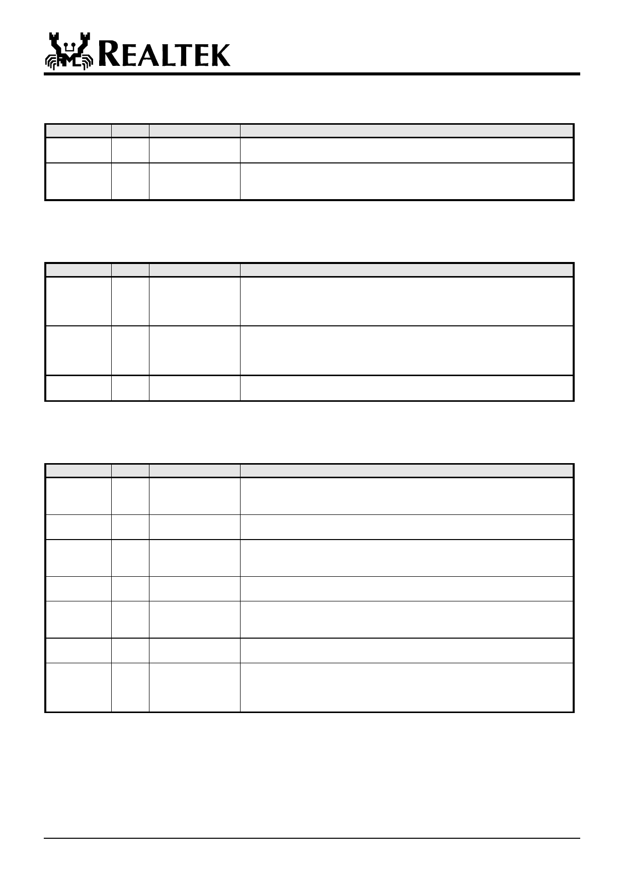
5.3 Clock Interface
Symbol
X2
Type
O
Pin No.
47
X1
I
46
Description
25MHz Crystal Output: This pin provides the 25MHz crystal output. It
must be left open when X1 is driven with an external 25MHz oscillator.
25MHz Crystal Input: This pin provides the 25MHz crystal input. If a
25MHz oscillator is used, connect X1 to the oscillator’s output. Refer to
section 8.3 to obtain clock source specifications.
5.4 100Mbps Network Interface
Symbol
TPTX+
TPTX-
Type
O
O
RTSET
I
TPRX+
I
TPRX-
I
Pin No.
34
33
28
31
30
Description
Transmit Output: Differential pair shared by 100Base-TX, 100Base-FX and
10Base-T modes. When configured as 100Base-TX, output is an MLT-3
encoded waveform. When configured as 100Base-FX, the output is
pseudo-ECL level.
Transmit Bias Resistor Connection: This pin should be pulled to GND by
a 5.9KΩ (1%) resistor to define driving current for transmit DAC. The
resistance value may be changed, depending on experimental results of the
RTL8201BL.
Receive Input: Differential pair shared by 100Base-TX, 100Base-FX, and
10Base-T modes.
5.5 Device Configuration Interface
Symbol
ISOLATE
Type
I
RPTR
I
SPEED
LI
DUPLEX
LI
ANE
LI
LDPS
I
MII/SNIB/ LI/O
RTT3(test)
Pin No.
43
40
39
38
37
41
44
Description
Set high to isolate the RTL8201BL from the MAC. This will also isolate the
MDC/MDIO management interface. In this mode, the power consumption is
minimum. This pin can be directly connected to GND or VCC.
Set high to put the RTL8201BL into repeater mode. This pin can be directly
connected to GND or VCC.
This pin is latched to input during a power on or reset condition. Set high to
put the RTL8201BL into 100Mbps operation. This pin can be directly connected
to GND or VCC.
This pin is latched to input during a power on or reset condition. Set high to
enable full duplex. This pin can be directly connected to GND or VCC.
This pin is latched to input during a power on or reset condition. Set high to
enable Auto-negotiation mode, set low to force mode. This pin can be directly
connected to GND or VCC.
Set high to put the RTL8201BL into LDPS mode. This pin can be directly
connected to GND or VCC. Refer to Section 7.7 for more information.
This pin is latched to input during a power on or reset condition. Pull high to
set the RTL8201BL into MII mode operation. Set low for SNI mode. This pin
can be directly connected to GND or VCC. In test mode, this pin is an output pin and
redefined as RTT3
2002-03-29
6
Rev.1.2
Share Link: 