USB2512I Ver la hoja de datos (PDF) - SMSC -> Microchip
Número de pieza
componentes Descripción
Lista de partido
USB2512I Datasheet PDF : 37 Pages
| |||
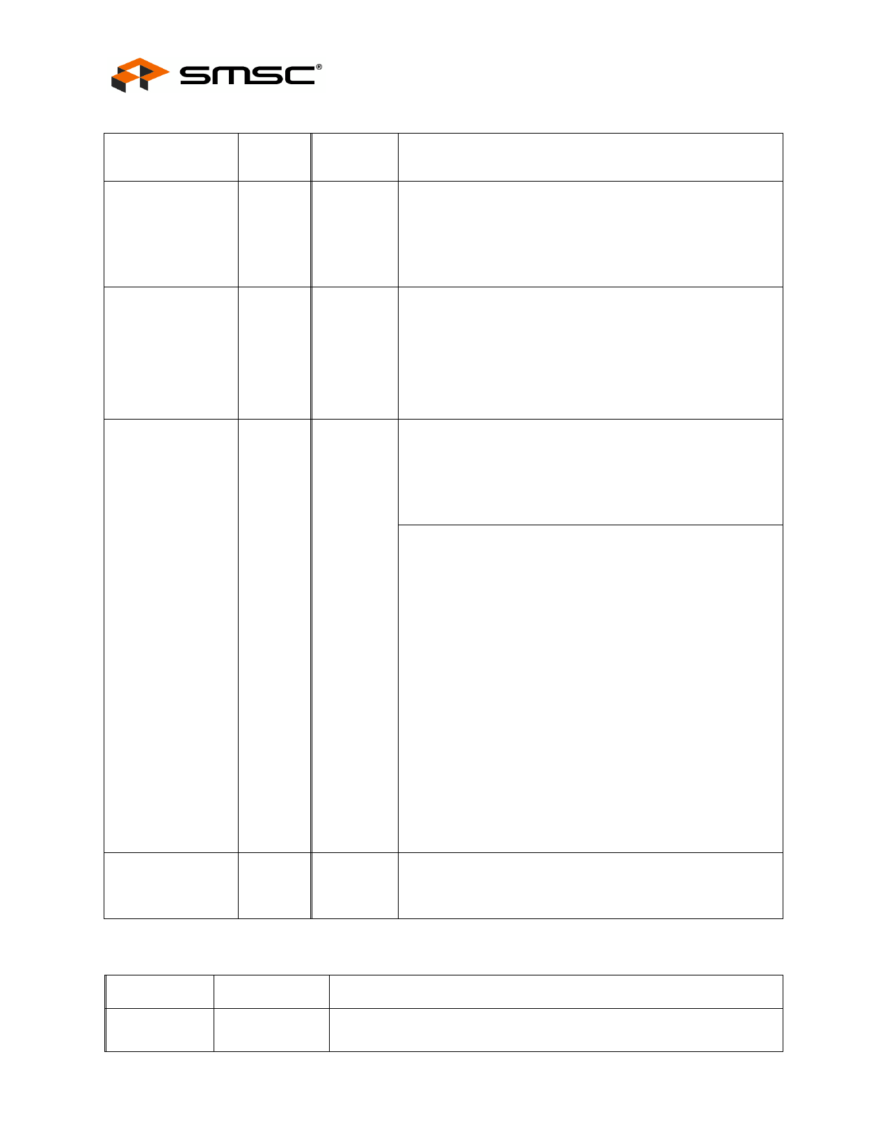
SYMBOL
XTAL2
RESET_N
SUSP_IND/
LOCAL_PWR/
NON_REM0
TEST
Industrial Temperature Rated USB 2.0 High-Speed 2-Port Hub Controller
Datasheet
Table 3.1 USB2512i Pin Descriptions (continued)
QFN-36
EMB
32
26
28
11
BUFFER
TYPE
OCLKx
IS
I/O
IPD
DESCRIPTION
Crystal Output
24MHz Crystal
This is the other terminal of the crystal, or a NO-CONNECT
when an external clock source is used to drive XTAL1/CLKIN.
This output must not be used to drive any external circuitry
other than the crystal circuit.
RESET Input
The system can reset the chip by driving this input low. The
minimum active low pulse is 1 us.
When the RESET_N pin is pulled to VDD33, the internal POR
(Power on Reset) is enabled and no external reset circuitry is
required. The internal POR holds the internal logic in reset until
the power supplies are stable.
Active/Suspend status LED or Local-Power & Non Removable
Strap Option
Suspend Indicator: Indicates USB state of the hub.
‘negated’ = Unconfigured, or configured and in USB Suspend
‘asserted’ = Hub is configured, and is active (i.e., not in
suspend)
Local Power: Detects availability of local self-power source.
Low = Self/local power source is NOT available (i.e., Hub gets
all power from Upstream USB VBus).
High = Self/local power source is available.
NON_REM0 Strap Option:
If this strap is enabled by package and configuration settings
(see Table 3.2), this pin will be sampled (in conjunction with
NON_REM1) at RESET_N negation to determine if ports [2:1]
contain permanently attached (non-removable) devices. Also,
the active state of the LED
will be determined as follows:
NON_REM[1:0] = ‘00’, All ports are removable, and the LED is
active high
NON_REM[1:0] = ‘01’, Port 1 is nonremovable, and the LED is
active low
NON_REM[1:0] = ‘10’, Ports 1 & 2 are non-removable, and the
LED is active high
NON_REM[1:0] = ‘11’, Ports 1 & 2 are non-removable, and the
LED is active low
TEST pin
Used for testing the chip. User must treat as a no-connect or
connect to ground.
CFG_SEL1
0
Table 3.2 SMBus or EEPROM Interface Behavior
CFG_SEL0
0
SMBUS OR EEPROM INTERFACE BEHAVIOR
Internal Default Configuration
Strap Options Enabled
Revision 1.92 (11-28-07)
10
DATASHEET
SMSC USB2512i
Share Link: 