TK10651MTL/10651 Ver la hoja de datos (PDF) - Toko America Inc
Número de pieza
componentes Descripción
Lista de partido
TK10651MTL/10651 Datasheet PDF : 12 Pages
| |||
TK10651
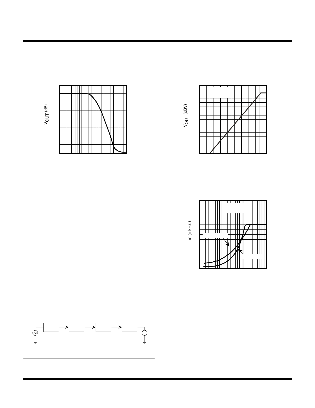
TYPICAL PERFORMANCE CHARACTERISTICS (CONT.)
THIRD ORDER LPF CHARACTERISTICS
OUTPUT VOLTAGE vs. THIRD
ORDER LPF INPUT FREQUENCY
10
0
-10
-20
-30
-40
-50
-60
-70
0.1 0.2 0.5 1 2 5 10 20 50 100
fIN (kHz)
OUTPUT VOLTAGE VS. THIRD
ORDER LPF INPUT VOLTAGE
0
VCC = 3.0 V
fIN = 1.0 kHz
-10
-20
-30
-40
-50
-60
-70
-90 -80 -70 -60 -50 -40 -30 -20 -10 0
VIN (dBV)
USING THE COMPANDOR TO IMPROVE S/N
This section provides an example of using the compandor
to improve S/N in a narrow band FM communication
system. In the test configuration below, the compressor
modulation level was measured as a function of the input
voltage to demonstrate the improvement resulting from the
use of the compressor. An audio signal is connected into
the compressor and the output is measured with the
modulation meter connected to the external modulation
input of the FM signal generator. The compressor's refer-
ence input level was set to produce ±3.0 kHz frequency
deviation. As shown in the graph on the right, the peak
deviation remains the same when the compressor is used,
but a wider input range is obtained. The built-in character-
istics of the IDC circuit limit the maximum frequency devia-
tion to ±4.5 kHz.
TEST CONFIGURATION
TK10651
FM
COMP
SG
FM IF IC
TK10487
TK10651
EXP
V
MODULATION LEVEL vs.
COMPRESSOR INPUT
7
VCC = 3.0 V
6
fMOD = 1.0 kHz
5
4
COMPRESSOR
3
2
THROUGH
1
0
0.1 0.2 0.5 1 2 5 10 20 50 100
VIN (mVrms)
January 2000 TOKO, Inc.
Page 7
Share Link: 