TK10651MTL/10651 Ver la hoja de datos (PDF) - Toko America Inc
Número de pieza
componentes Descripción
Lista de partido
TK10651MTL/10651 Datasheet PDF : 12 Pages
| |||
TK10651
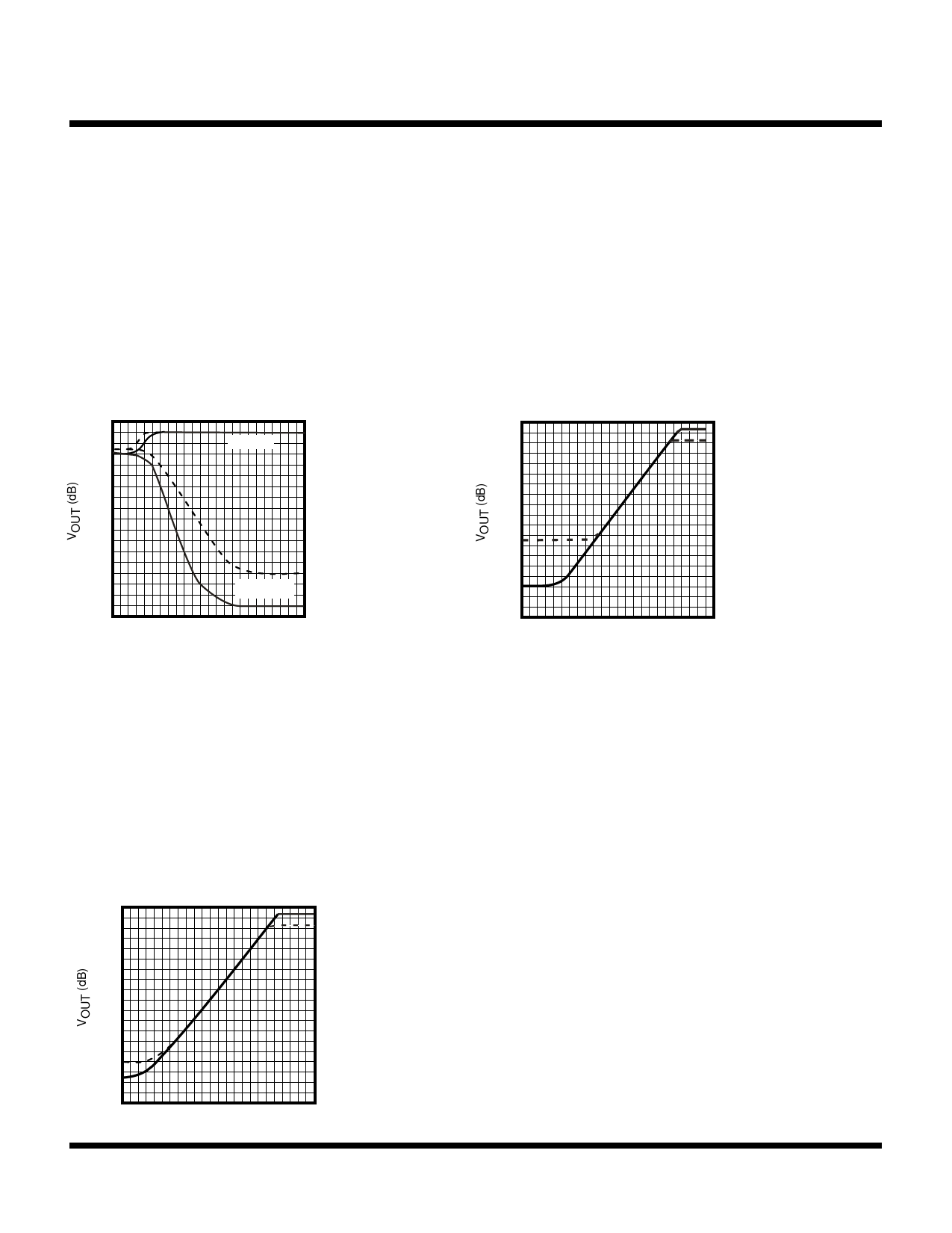
TYPICAL PERFORMANCE CHARACTERISTICS (CONT.)
USING THE COMPANDOR TO IMPROVE S/N (CONT.)
The improvement resulting from the expander is expressed
by measuring the overall characteristics of the FM IF
System (TK10487M). The signal generator was switched
to internal modulation and the output is defined as 0 dB
when the RF input = 80 dBµ. As the graph below indicates,
the noise is reduced when the expander is used, and good
S/N ratio is maintained even when the RF signal input is
weak.
OUTPUT VOLTAGE RATIO vs.
COMPANDOR RF INPUT
0
-10
-20
-30
-40
-50
-60
-70
-80
-20 0
SIGNAL
NOISE
VCC = 3.0 V
fOSC = 10.245 MHz
DEV = ± 3.0 kHz
fMOD = 1.0 kHz
FILTER : CCITT P.53
IF IC : TK10487M
NO PRE-EMPHASIS
OR DE-EMPHASIS
SOLID LINE:
COMPRESSOR
DASHED LINE: THROUGH
20 40 60 80 100
VIN (dBu)
The following graph shows the characteristics when the RF
input is weak (RF IN = 30 dBµ). There is a great difference
when the compandor is used with a weak RF input. When
the through function is used (noise reduction off), the output
is lost in noise as the compressor input drops below –80
dBV; but when the compandor function is used, it remains
level below –100 dBV. With a weak RF input, dynamic
range is extended by 30 dB.
OUTPUT VOLTAGE RATIO
(FOR WEAK RF INPUT SIGNAL)
vs. COMPANDOR INPUT
10
0
-10
-20
-30
-40
-50
-60
-70
-80 -110 -90 -70 -50 -30 -10
VIN (dBV)
VCC = 3.0 V
fOSC = 10.245 MHz
fMOD = 1.0 kHz
FILTER : CCITT P.53
IF IC :TK10487M
NO PRE-EMPHASIS
OR DE-EMPHASIS
SOLID LINE:
COMPRESSOR
DASHED LINE: THROUGH
Finally, the overall characteristics are measured using both
the compressor and the expander. The output is measured
when the compressor's input is at –40 dBµV and the
frequency deviation is ±3.0 kHz.
The graph below shows the characteristics when the RF
input is strong (RF IN = 80 dBµ). The dynamic range is
increased by more than 12 dB when the compandor is
used.
The effects of the compandor within a narrow band FM
communications system was demonstrated while a coaxial
cable was used in place of transmission through free
space. The signal source was an FM signal generator
although there are some differences when actual transmis-
sion is through free space. However, the test configuration
used in this experiment is useful in understanding the
effects of the compandor.
OUTPUT VOLTAGE RATIO (FOR
STRONG RF INPUT SIGNAL)
vs. COMPANDOR RF INPUT
10
0
-10
-20
-30
-40
-50
-60
-70
-80 -120
-90 -70 -50 -30 -10
VIN (dBV)
VCC = 3.0 V
fOSC = 10.245 MHz
fMOD = 1.0 kHz
FILTER : CCITT P.53
IF IC :TK10487M
NO PRE-EMPHASIS
OR DE-EMPHASIS
SOLID LINE:
COMPRESSOR
DASHED LINE: THROUGH
Page 8
January 2000 TOKO, Inc.
Share Link: 