PI74FCT2841T Ver la hoja de datos (PDF) - Pericom Semiconductor
Número de pieza
componentes Descripción
Lista de partido
PI74FCT2841T Datasheet PDF : 7 Pages
| |||
PI74FCT841T/843T/845T
(25Ω SERIES) P174FCT2841T
BUS INTERFACE LATCHES 1122334455667788990011223344556677889900112233445566778899001122112233445566778899001122334455667788990011223344556677889900112211223344556677889900112233445566778899001122334455667788990011221122334455667788990011223344556677889900112233445566778899001122112233445566778899001122
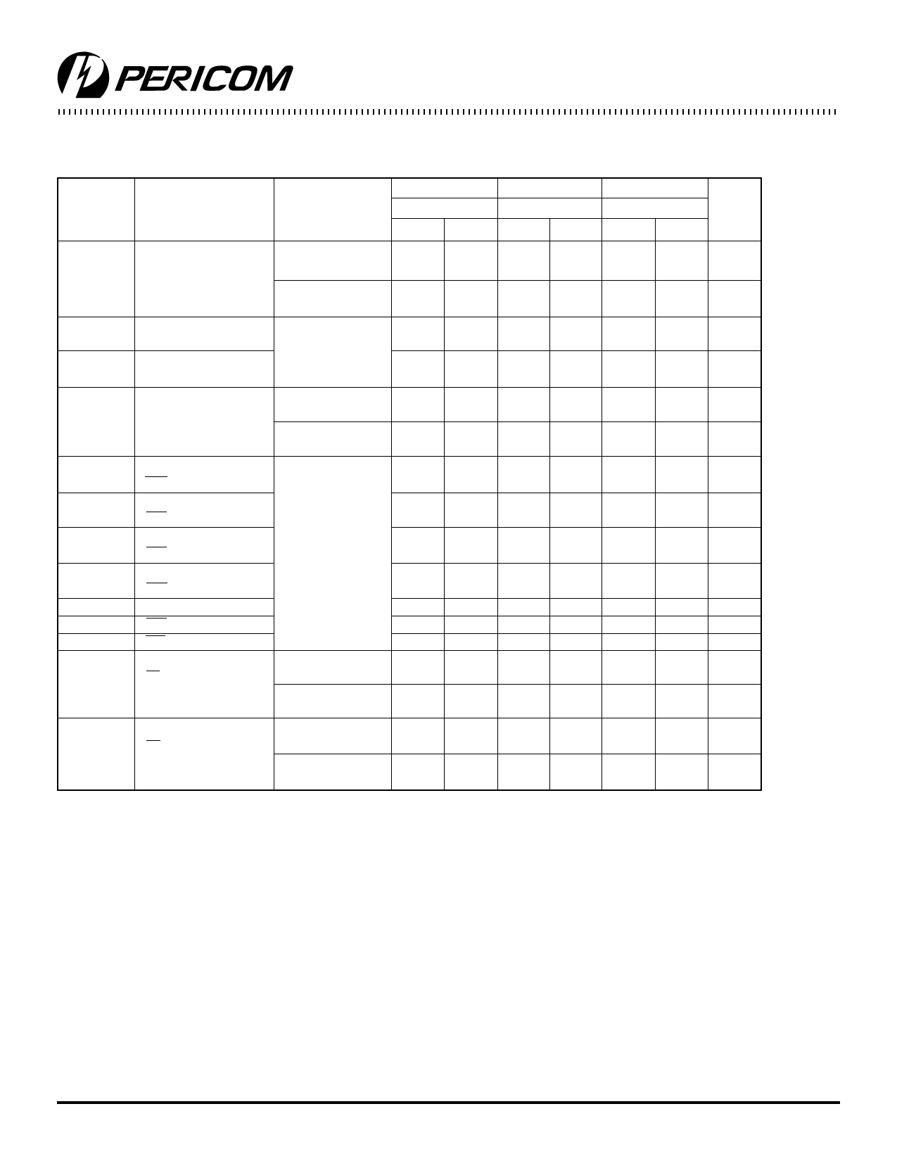
PI74FCT845T Switching Characteristics over Operating Range
Parameters Description
845AT
845BT
845CT
Com.
Com.
Com.
Conditions(1) Min
Max
Min
Max
Min
Max
Unit
tPLH
Propagation Delay
tPHL
DN to YN
CL = 50 pF
RL = 500Ω
(LE = HIGH)
CL = 300 pF(3)
RL = 500Ω
tSU
Setup Time
Data to LE
CL = 50 pF
RL = 500Ω
tH
Hold Time
Data to LE
tPLH
Propagation Delay
tPHL
LE to YN
CL = 50 pF
RL = 500Ω
CL = 300 pF(3)
RL = 500Ω
tPLH
Propagation Delay
PRE to YN
tREM
Recovery Time(3)
CL = 50 pF
RL = 500Ω
PRE to YN
tPLH
Propagation Delay
CLR to YN
tREM
Recovery Time(3)
CLR to YN
tW
LE Pulse Width(3) (HIGH)
tW
PRE Pulse Width(3) (LOW)
tW
CLR Pulse Width(3) (LOW)
tPZH
Output Enable Time
CL = 50 pF
tPZL
OE to YN
RL = 500Ω
CL = 300 pF(3)
RL = 500Ω
tPHZ
Output Disable Time(3)
CL = 50 pF
tPLZ
OE to YN
RL = 500Ω
CL = 5 pF(3)
RL = 500Ω
1.5
9.0
1.5
6.5
1.5
5.5
ns
1.5
8.0
1.5
13.0
1.5
13.0
ns
2.5
—
2.5
—
2.5
—
ns
2.5
—
2.5
—
2.5
—
ns
1.5
12.0
1.5
8.0
1.5
6.4
ns
1.5
16.0
1.5
15.5
1.5
15.0
ns
1.5
11.0
1.5
8.0
1.5
7.0
ns
1.5
11.0
1.5
10.0
1.5
9.0
ns
1.5
11.0
1.5
10.0
1.5
9.0
ns
1.5
13.0
1.5
10.0
1.5
9.0
ns
4.0
—
4.0
—
4.0
—
ns
5.0
—
4.0
—
4.0
—
ns
4.0
—
4.0
—
4.0
—
ns
1.5
10.0
1.5
8.0
1.5
6.5
ns
1.5
23.0
1.5
14.0
1.5
12.0
ns
1.5
7.0
1.5
6.5
1.5
5.7
ns
1.5
8.0
1.5
7.0
1.5
6.0
ns
Notes:
1. See test circuit and wave forms.
2. Minimum limits are guaranteed but not tested on Propagation Delays.
3. This parameter is guaranteed but not production tested.
Pericom Semiconductor Corporation
2380 Bering Drive • San Jose, CA 95131 • 1-800-435-2336 • Fax (408) 435-1100 • http://www.pericom.com
7
PS2025A 03/11/96
Share Link: 