RF2461 Ver la hoja de datos (PDF) - RF Micro Devices
Número de pieza
componentes Descripción
Lista de partido
RF2461 Datasheet PDF : 14 Pages
| |||
RF2461
Preliminary
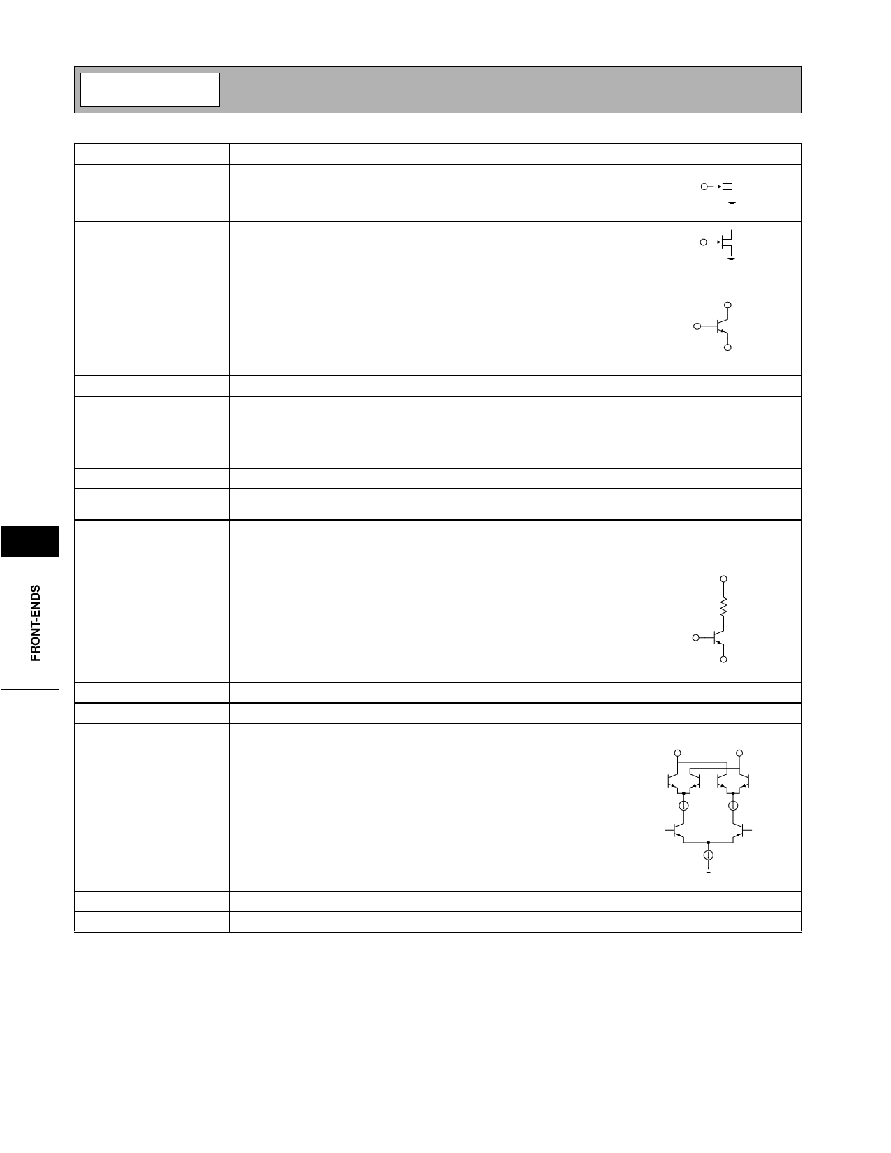
Pin Function Description
Interface Schematic
1
LNA GAIN Controls the bypass feature of the LNA. A logic low (<1.0V) selects the
bypass mode. A logic high (>2.0V) turns on the LNA.
LNA GAIN
2
MIX GAIN Controls the bypass feature of the mixer pre-amp. A logic low (<1.0V)
selects the bypass mode. A logic high (>2.0V) turns on the pre-amp.
MIX GAIN
3
LNA IN LNA input pin.
LNA OUT
LNA IN
GND1B
4
VCC1
VCC pin for all circuits except the LO. Buffer/bias circuitry.
5
GND1B LNA emitter. This pin provides the DC path to ground for the LNA. A
lumped element or a transmission line inductor can be placed between
this pin and ground to degenerate the LNA. This will decrease the gain,
increase the IP3, and increase the NF of the LNA. As the value of
inductance is increased, these effects will become more pronounced.
6
LNA OUT LNA output pin.
See pin 3.
7
ISET2
An external resistor R2 connected to this pin sets the current of the pre-
amp and the mixer.
8
8
ISET1
An external resistor R3 connected to this pin sets the current of the
LNA when IP SET is high (see pin 19).
9
GND3B Ground pin for pre-amp circuit. A 3.3nH inductor is used between pin 9
and ground to degenerate the mixer pre-amp. Degenerating the pre-
VCC2
amp will reduce the gain, increase the IP3 and affect the pre-amp input
impedance.
MIX IN
GND3B
10
MIX IN
Mixer pre-amp input pin.
See pin 9.
11
IF1-
Second differential output pin for the first mixer.
See pin 12.
12
IF1+
First differential output pin for the first mixer. Open collector. A current
combiner external network performs a differential to single-ended con-
version and sets the output impedance. A DC blocking cap must be
present if the IF filter input has a DC path to ground. Mixer (IF2+ and
IF-) needs to “see” a differential impedance between 2kΩ to 4kΩ.
IF1-
IF1+
13
BYPASS Bypass pin for the LO bias reference.
14
IF2-
Second differential output pin for the second mixer.
See pin 15.
8-126
Rev A13 010607
Share Link: 