MD1320N Ver la hoja de datos (PDF) - Unspecified
Número de pieza
componentes Descripción
Lista de partido
MD1320N Datasheet PDF : 24 Pages
| |||
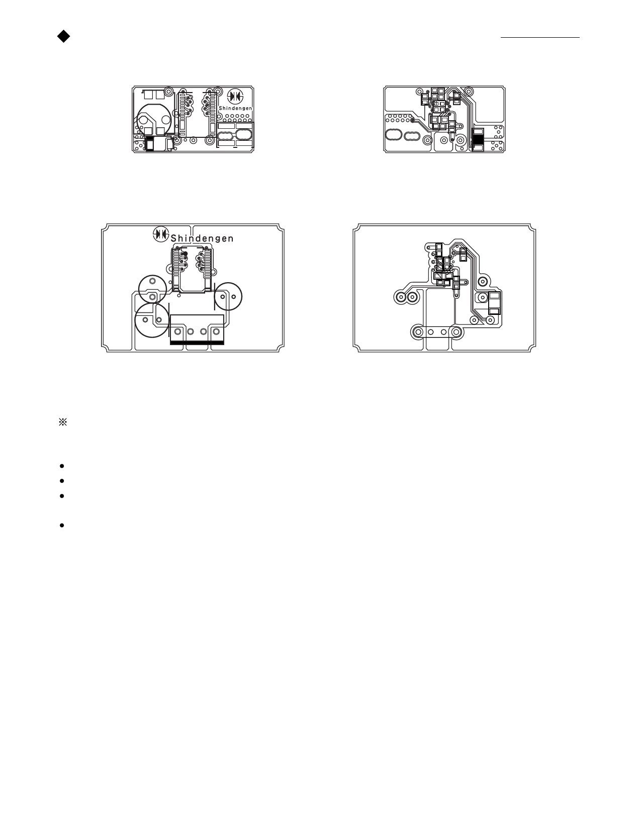
5 - 3 Printed circuit board patterns and design considerations(Reference)
L1
IC1 MD
C5
+Vo G +Vin C1-1 C1-2
R3
C6
R1
C2
3.3V5V
D1K
C3 C4
R2
Typical 1.5A surface mounted parts model
MD
L1
C1
IC1
CN1
C5
+Vo G +Vin
R1
3.3V5V
D1K
C3
C2
C4
R2
Typical 1.5A lead parts model
The device does not have a voltage surge protection circuit or an input fuse. The user should install an input fuse to protect the device and
equipment before using the device.
For optimum thermal efficiency, maintain the copper foil pattern as much as possible.
Connect the F/B OCL negative terminal (Pin 2) as close as possible to the output capacitor (C5).
Connect the input capacitor (C1), output capacitor (C5), choke (L1), and dropping resistor (R2) as close as possible to the power IC
device.
Separate the ground terminals (Pin 4 and Pin 26) and the P and ground terminals (Pins 16). Connect each of them as close as possible
to output capacitor (C5).
8
Share Link: 