ISL8500 Ver la hoja de datos (PDF) - Renesas Electronics
Número de pieza
componentes Descripción
Lista de partido
ISL8500 Datasheet PDF : 15 Pages
| |||
ISL8500
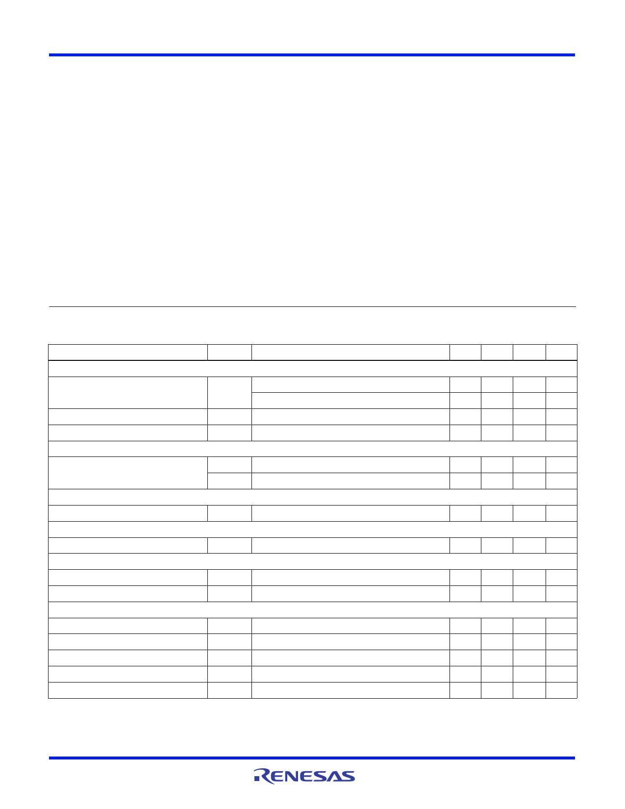
Absolute Maximum Ratings (Note 1)
VIN . . . . . . . . . . . . . . . . . . . . . . . . . . . . . . . . . . . . . . . . -0.3V to 26V
BOOT to GND . . . . . . . . . . . . . . . . . . . . . . . . . . . . . . . -0.3V to 33V
BOOT to PHASE . . . . . . . . . . . . . . . . . . . . . . . . . . . . . . -0.03V to 6V
VDD, FB, EN, COMP, PG, SS . . . . . . . . . . . . . . . . . . . . -0.3V to 6V
Recommended Operating Conditions
VIN Supply Voltage Range . . . . . . . . . . . . . . . . . . . . . . 4.5V to 25V
Load Current Range . . . . . . . . . . . . . . . . . . . . . . . . . . . . . . 0A to 2A
Ambient Temperature Range . . . . . . . . . . . . . . . . . . . . -40°C to +85°
Thermal Information
Thermal Resistance
JA (°C/W) JC (°C/W)
QFN Package (Notes 1, 2). . . . . . . . . .
39
3
Ambient Temperature Range. . . . . . . . . . . . . . . . . . .-40°C to +85°C
Junction Temperature Range. . . . . . . . . . . . . . . . . .-40°C to +125°C
Storage Temperature Range . . . . . . . . . . . . . . . . . .-65°C to +150°C
Pb-free reflow profile . . . . . . . . . . . . . . . . . . . . . . . . . .see link below
http://www.intersil.com/pbfree/Pb-FreeReflow.asp
CAUTION: Do not operate at or near the maximum ratings listed for extended periods of time. Exposure to such conditions may adversely impact product reliability and
result in failures not covered by warranty.
NOTES:
1. JA is measured in free air with the component mounted on a high effective thermal conductivity test board with “direct attach” features. See
Tech Brief TB379 for details.
2. For JC, the “case temp” location is the center of the exposed metal pad on the package underside. See Tech Brief TB379 for details.
3. Test Condition: VIN = 15V, FB forced above regulation point (0.6V), no switching, and power MOSFET gate charging current not included.
4. Excluding the blanking time.
5. Specifications at -40°C to +85°C are established by +25°C test with margin limits.
Electrical Specifications
PARAMETER
Unless Otherwise Noted, All Parameter Limits are Established Over the Recommended Operating Conditions
and the Typical Specifications are Measured at the Following Conditions: TA = -40°C To +85°C (Note 5),
VIN = 5.5V to 25V, Unless Otherwise Noted. Typical Values are at TA = +25°C.
SYMBOL
TEST CONDITIONS
MIN TYP MAX UNITS
SUPPLY VOLTAGE
VIN Voltage Range
VIN
5.5
-
25
V
VIN connected to VDD
4.5
5.0
5.5
V
VIN Operating Supply Current
VIN Shutdown Supply Current
POWER-ON RESET
IOP
Note 3
ISD
VIN = 15V, EN = GND
-
2
2.5 mA
-
80
100
µA
VDD POR Threshold
Rising Edge
4.00 4.15 4.30
V
Hysteresis
-
275
-
mV
INTERNAL VDD LDO
VDD Output Voltage Range
REFERENCE
VIN = 5.5V to 25V, IVDD = 0mA to 30mA
4.5 5.00 5.5
V
Reference Voltage
STANDARD BUCK PWM REGULATOR
VFB VIN = 5.5V to 25V, IREF = 0
0.594 0.6 0.606 V
FB Line Regulation
FB Leakage Current
OSCILLATOR AND PWM MODULATOR
IOUT = 0mA, VIN = 5.5V to 25V
VFB = 0.6V
-0.05
-
-50
0
0.05
%
50
nA
Nominal Switching Frequency
Modulator Gain
Peak-to-Peak Sawtooth Amplitude
PWM Ramp Offset Voltage
Maximum Duty Cycle
fSW
AMOD VIN = 12V (AMOD = 8/VIN)
VRAMP VIN = 12V (VP-P = VIN/8)
VOFFSET
DCmax COMP > 4V
450 500 550 kHz
0.65 0.75 0.95 V/V
-
1.3
-
V
0.75 0.8 0.85
V
80
-
-
%
FN6611 Rev 0.00
December 10, 2007
Page 4 of 15
Share Link: 