ICS9248F-50-T Ver la hoja de datos (PDF) - Integrated Circuit Systems
Número de pieza
componentes Descripción
Lista de partido
ICS9248F-50-T Datasheet PDF : 11 Pages
| |||
ICS9248-50
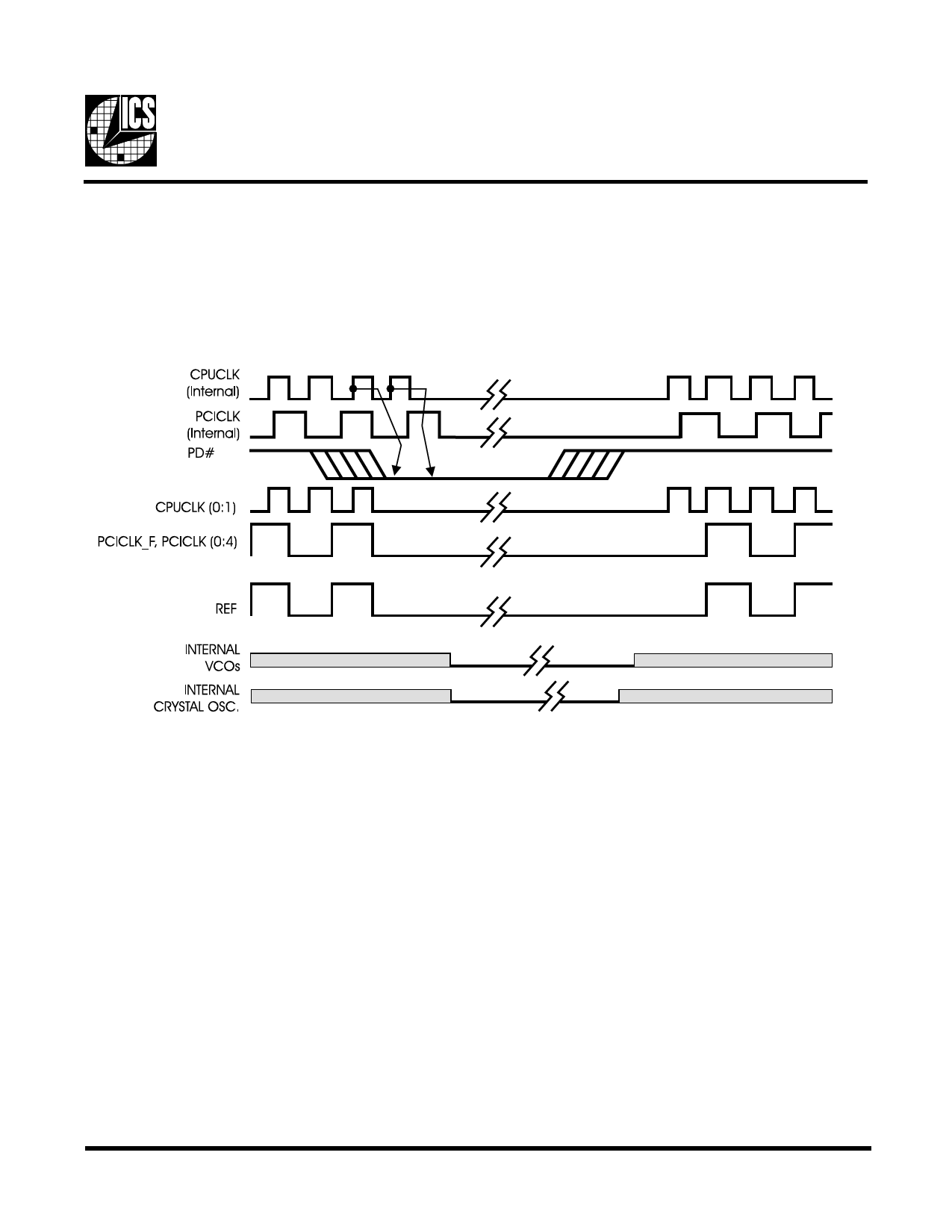
PD# Timing Diagram
The power down selection is used to put the part into a very low power state without turning off the power to the part. PD# is
an asynchronous active low input. This signal is synchronized internally by the ICS9248-50 prior to its control action of
powering down the clock synthesizer. Internal clocks will not be running after the device is put in power down state. When
PD# is active (low) all clocks are driven to a low state and held prior to turning off the VCOs and the crystal oscillator. The
power on latency is guaranteed to be less than 3ms. The power down latency is less than three CPUCLK cycles. PCI_STOP#
and CPU_STOP# are don’t care signals during the power down operations.
Notes:
1. All timing is referenced to the Internal CPUCLK (defined as inside the ICS9248 device).
2. PD# is an asynchronous input and metastable conditions may exist. This signal is synchronized inside the ICS9248.
3. The shaded sections on the VCO and the Crystal signals indicate an active clock is being generated.
5
Share Link: 