RMWB12001 Ver la hoja de datos (PDF) - Raytheon Company
Número de pieza
componentes Descripción
Lista de partido
RMWB12001 Datasheet PDF : 6 Pages
| |||
RMWB12001
12 GHZ Buffer Amplifier MMIC
Recommended
Procedure
for Biasing and
Operation
PRODUCT INFORMATION
CAUTION: LOSS OF GATE VOLTAGE (Vg) WHILE DRAIN VOLTAGE (Vd) IS PRESENT MAY DAMAGE THE
AMPLIFIER CHIP.
The following sequence of steps must be followed to properly test the amplifier.
Step 1: Turn off RF input power.
Step 2: Connect the DC supply grounds to the grounds
of the chip carrier. Slowly apply negative gate
bias supply voltage of -1.5 V to Vg.
Step 3: Slowly apply positive drain bias supply voltage
of +4 V to Vd.
Step 4: Adjust gate bias voltage to set the quiescent
current of Idq=96 mA.
Step 5: After the bias condition is established, RF input
signal may now be applied at the appropriate
frequency band.
Step 6: Follow turn-off sequence of:
(i) Turn off RF input power,
(ii) Turn down and off drain voltage (Vd),
(iii) Turn down and off gate bias voltage (Vg).
Performance
Data
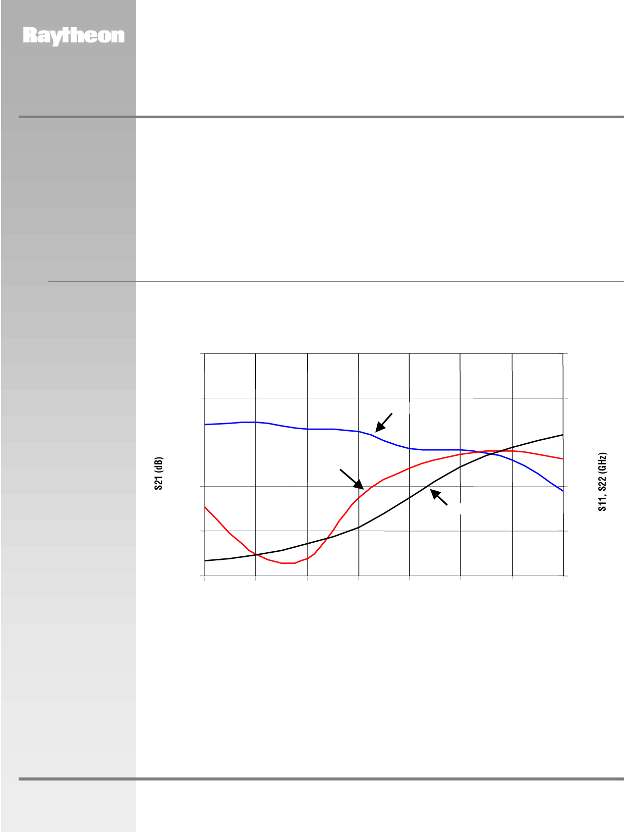
RMWB12001 12 GHz BA, Typical Small Signal Performance
On-Wafer Measurements, Vd=4 V, Idq= 96 mA
30
0
28
-5
S21
26
-10
S11
24
-15
S22
22
-20
20
-25
8.5
9.0
9.5
10.0
10.5
11.0
11.5
12.0
Frequency (GHz)
www.raytheon.com/micro
Characteristic performance data and specifications are subject to change without notice.
Revised March 14, 2001
Page 4
Raytheon RF Components
362 Lowell Street
Andover, MA 01810
Share Link: 