XR16C864CQ(2004) Ver la hoja de datos (PDF) - Exar Corporation
Número de pieza
componentes Descripción
Lista de partido
XR16C864CQ Datasheet PDF : 51 Pages
| |||
áç
REV. 2.0.1
XR16C864
2.97V TO 5.5V QUAD UART WITH 128-BYTE FIFO
TABLE 2: CHANNEL A-D SELECT IN 68 MODE
CS# A4 A3
1 N/A N/A
0
0
0
0
0
1
0
1
0
0
1
1
FUNCTION
UART de-selected
Channel A selected
Channel B selected
Channel C selected
Channel D selected
2.6 Channels A-D Internal Registers
Each UART channel in the 864 has a set of enhanced registers for control, monitoring and data loading and
unloading. The configuration register set is compatible to those already available in the standard single
16C550. These registers function as data holding registers (THR/RHR), interrupt status and control registers
(ISR/IER), a FIFO control register (FCR), receive line status and control registers (LSR/LCR), modem status
and control registers (MSR/MCR), programmable data rate (clock) divisor registers (DLL/DLM), and a user
accessible scratchpad register (SPR).
Beyond the general 16C550 features and capabilities, the 864 offers enhanced feature registers (EMSR, FLVL,
EFR, Xon/Xoff 1, Xon/Xoff 2, FCTR, TRG, FC) that provide automatic RTS and CTS hardware flow control,
Xon/Xoff software flow control, automatic RS-485 half-duplex direction output enable/disable, FIFO trigger
level control, and FIFO level counters. All the register functions are discussed in full detail later in “Section 3.0,
UART INTERNAL REGISTERS” on page 22.
2.7 INT Ouputs for Channels A-D
The interrupt outputs change according to the operating mode and enhanced features setup. Table 3 and 4
summarize the operating behavior for the transmitter and receiver. Also see Figure 19 through 23.
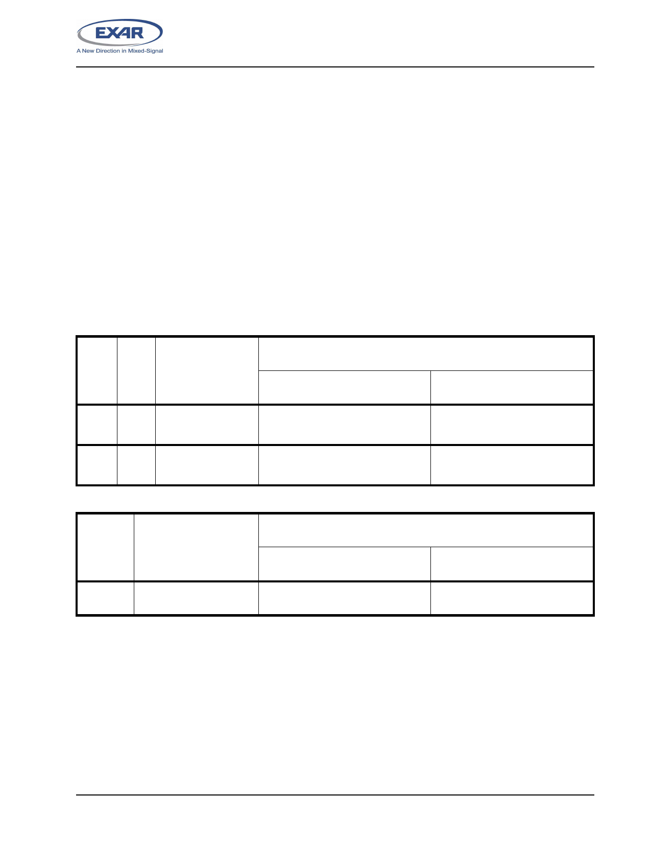
TABLE 3: INT PINS OPERATION FOR TRANSMITTER FOR CHANNELS A-D
FCTR
Bit-3
FCR BIT-0 = 0
(FIFO DISABLED)
FCR BIT-0 = 1 (FIFO ENABLED)
INT Pin
0 0 = a byte in THR
1 = THR empty
INT Pin
1 0 = a byte in THR
1 = transmitter empty
FCR Bit-3 = 0
(DMA Mode Disabled)
FCR Bit-3 = 1
(DMA Mode Enabled)
0 = FIFO above trigger level
1 = FIFO below trigger level or FIFO
empty
0 = FIFO above trigger level
1 = FIFO below trigger level or
transmitter empty
0 = FIFO above trigger level
1 = FIFO below trigger level or FIFO
empty
0 = FIFO above trigger level
1 = FIFO below trigger level or
transmitter empty
TABLE 4: INT PIN OPERATION FOR RECEIVER FOR CHANNELS A-D
FCR BIT-0 = 0
(FIFO DISABLED)
FCR BIT-0 = 1 (FIFO ENABLED)
INT Pin 0 = no data
1 = 1 byte
FCR Bit-3 = 0
(DMA Mode Disabled)
0 = FIFO below trigger level
1 = FIFO above trigger level
FCR Bit-3 = 1
(DMA Mode Enabled)
0 = FIFO below trigger level
1 = FIFO above trigger level
11
Share Link: 