XR16C864CQ(2004) Ver la hoja de datos (PDF) - Exar Corporation
Número de pieza
componentes Descripción
Lista de partido
XR16C864CQ Datasheet PDF : 51 Pages
| |||
áç
XR16C864
2.97V TO 5.5V QUAD UART WITH 128-BYTE FIFO
APRIL 2004
GENERAL DESCRIPTION
FEATURES
REV. 2.0.1
The XR16C8641 (864) is an enhanced quad
Universal Asynchronous Receiver and Transmitter
(UART) each with 128 bytes of transmit and receive
FIFOs, transmit and receive FIFO counters and
trigger levels, automatic hardware and software flow
control, automatic RS-485 half-duplex direction
control and data rates of up to 2 Mbps. Each UART
has a set of registers that provide the user with
operating status and control, receiver error
indications, and modem serial interface controls.
System interrupts may be tailored to meet design
requirements. An internal loopback capability allows
onboard diagnostics. The 864 is available in the 100-
pin QFP package. The XR16C864 offers faster
channel status access by providing separate outputs
for TXRDY and RXRDY, offer separate Infrared TX
outputs and a separate clock input for channel C
(CHCCLK). The XR16C864 is compatible with the
industry standard ST16C554/554D, ST16C654/654D
and XR16C854/854D.
NOTE: 1 Covered by U.S. Patent #5,649,122 and #5,949,787.
Added feature in devices with top mark date code of
"F2 YYWW" and newer:
s 5 volt tolerant inputs
• 2.97 to 5.5 Volt Operation
• Pin-to-pin compatible with the industry standard
ST16C554 and ST16C654 and TI’s TL16C554N
and TL16C754BFN
• Intel or Motorola Data Bus Interface select
• Four independent UART channels
s Register Set Compatible to 16C550
s Data rates of up to 2 Mbps
s Transmit and Receive FIFOs of 128 bytes
s Programmable TX and RX FIFO Trigger Levels
s Transmit and Receive FIFO Level Counters
s Automatic Hardware (RTS/CTS) Flow Control
s Selectable Auto RTS Flow Control Hysteresis
s Automatic Software (Xon/Xoff) Flow Control
s Wireless Infrared (IrDA 1.0) Encoder/Decoder
• Sleep Mode (200 uA typical)
• Crystal oscillator or external clock input
APPLICATIONS
• Portable Appliances
• Telecommunication Network Routers
• Ethernet Network Routers
• Cellular Data Devices
• Factory Automation and Process Controls
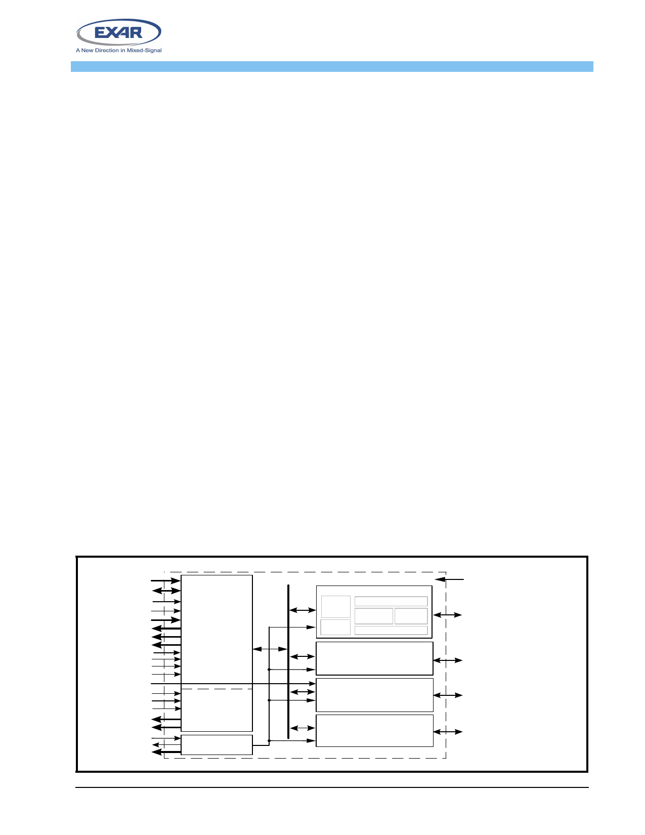
FIGURE 1. XR16C864 BLOCK DIAGRAM
A2:A0
D7:D0
IOR#
IO W #
CS# A-D
INT A-D
TXRDY# A-D
RXRDY# A-D
Reset
16/68#
INTSEL
CLKSEL
CHCCLK
TC
AEN
DACK A-D
TXDRQ# A-D
RXDRQ# A-D
XTAL1
XTAL2
BCLK A-D
Intel or
M o to ro la
Data Bus
Interface
Direct
Memory
Access
Crystal Osc/Buffer
5V tolerant inputs (except XTAL1)
UART Channel A
UART
Regs
BRG
128 Byte TX FIFO
TX & RX
IR
ENDEC
128 Byte RX FIFO
UART Channel B
(same as Channel A)
UART Channel C
(same as Channel A)
UART Channel D
(same as Channel A)
2.97V to 5.5V VCC
TXA, RXA, IRTXA, DTRA#,
DSRA#, RTSA#, CTSA#,
CDA#, RIA#, OP2A#,
OP1A#/RS-485
TXB, RXB, IRTXB, DTRB#,
DSRB#, RTSB#, CTSB#,
CDB#, RIB#, OP2B#,
OP1B#/RS-485
TXC, RXC, IRTXC, DTRC#,
DSRC#, RTSC#, CTSC#,
CDC#, RIC#, OP2C#,
OP1C#/RS-485
TXD, RXD, IRTXD, DTRD#,
DSRD#, RTSD#, CTSD#,
CDD#, RID#, OP2D#,
OP1D#/RS-485
854 BLK
Exar Corporation 48720 Kato Road, Fremont CA, 94538 • (510) 668-7000 • FAX (510) 668-7017 • www.exar.com
Share Link: 