CDP1020 Ver la hoja de datos (PDF) - Intersil
Número de pieza
componentes Descripción
Lista de partido
CDP1020 Datasheet PDF : 23 Pages
| |||
CDP1020
LOCK_CTL
SFTLOCK
LEVEL MODE
SFTLOCK
PULSE MODE
SOLENOID
PULSE
WIDTH
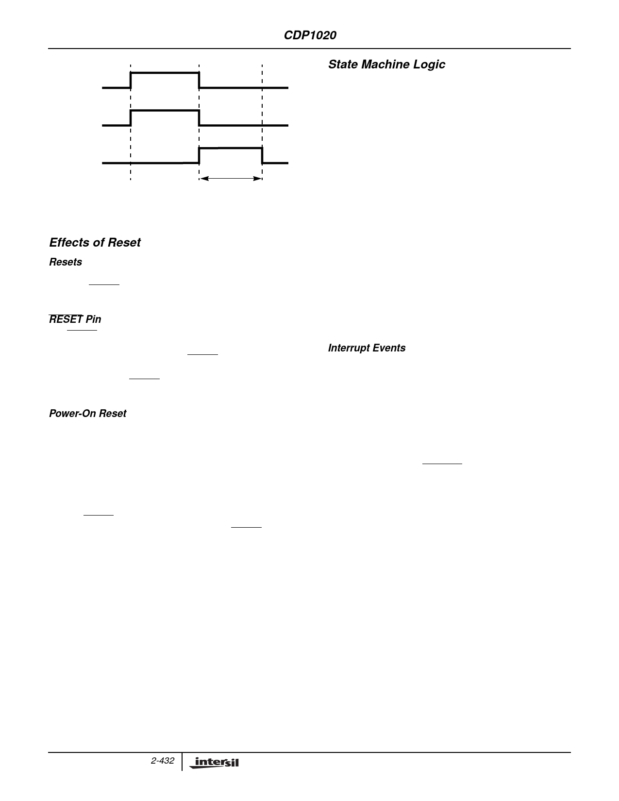
FIGURE 8. LOCK_CTL BIT/SFTLOCK OUTPUT
RELATIONSHIP IN LEVEL AND PULSE MODES
Effects of Reset
Resets
The CDP1020 has two reset modes: an active low external
reset pin (RESET) and an internal power-on reset function.
Both are logically OR’ed together internally.
RESET Pin
The RESET input pin is used to provide an orderly start-up
procedure and return the CDP1020 to a known state. When
using the external reset mode, the RESET pin must stay low
for a minimum of six (6) oscillator cycles (typically 1.5µs with
a 4MHz clock). The RESET pin contains an internal Schmitt
Trigger to improve noise immunity.
Power-On Reset
The internal power-on reset occurs when a positive
transition is detected on VDD. The power-on reset is used
strictly for power turn-on conditions and should not be used
to detect any drops in the power supply voltage. There is no
provision for a power-down reset.
The power-on circuitry provides a two oscillator cycle delay
from the time that the oscillator becomes active. If the
external RESET pin is low at the end of the time out, the
CDP1020 remains in the reset condition until RESET goes
high. The following list contains the actions of reset on
internal circuits, but not necessarily in order of occurrence.
• BCER0 and BCER1 reset to $00000000
• BSTR0 and BSTR1 reset to $00000000
• SFR reset to $00000000
• All PWREN, SFTLOCK, and LED outputs cleared
• DBCCR set to two bays, no security locks - $00000002
• All Write-Once permissions reset
• AD0 and AD1 inputs sampled for I2C/SMBus address
• Internal address pointer reset to $00
State Machine Logic
The CDP1020 contains two functionally identical state
machine logic blocks, one for each bay. Each of these blocks
is responsible for monitoring external Device Bay events
(i.e., device insertion, device removal, remove requests),
controlling the locking mechanism and power enable signal
for each bay, updating the state of the bay in response to OS
commands and external events as shown in Figure 9.
There are five separate functional states that each bay of the
CDP1020 can be in at any one time. Each of the two bay
controllers within the CDP1020 functions completely
independently of the other. The following sections detail state
machine operation in each of the five states, including state
transitions, operating system responsibility, and I/O functions.
In the following sections, the bay state controller will be referred
to generically; that is as a bay “x” controller. Thus, bay “x” has a
control register BCERx, a status register BSTRx, and so on.
The state of the device bay controller is changed through
either hardware events (device inserted, device removed)
and software events (OS writes into CDP1020 registers can
change the bay state under certain conditions).
Interrupt Events
An interrupt event is defined as one of the following:
• The insertion of a device into a bay with the corresponding
DEVSTSCHG_EN bit set
• Removal of a device after the insertion time-out in any
state other than Removal Allowed and the
DEVSTSCHG_EN bit is set
• Removal of a device in the Removal Allowed state with
both the REMWAKEVT and DEVSTSCHG_EN flags set
• User assertion of the REMREQ input when the associated
REMREQ_EN bit is set and a device is present in the bay
2-432
Share Link: 