PFS726 Ver la hoja de datos (PDF) - Power Integrations, Inc
Número de pieza
componentes Descripción
Lista de partido
PFS726 Datasheet PDF : 30 Pages
| |||
PFS704-729EG
1.2
1
Soft-Start
Check
Sequence
0.8
0.6
0.4
0.2
0
0
0.2
0.4 0.6
0.8
1
1.2 1.4
Figure 5.
Normalized to Peak Power Rating
Typical Normalized Output Voltage Characteristics as Function of
Normalized Peak Load Rating
VCC+
Is
NO
VCC >
VCC+
YES
Apply 0.5 μA
on FB to
Check Open FB
Is
VFB > FBOFF
NO
and
VFB < FBOV
YES
NO
Is IV > IUV+
Apply
6 mA V Pin
Current Sink
Detect Input
Voltage Peak
NO
Is VFB > FBOFF
Start
Converter
YES
Remove
6 mA V Pin
Current Sink
Slew Power-Limit
Over Soft-Start
Duration
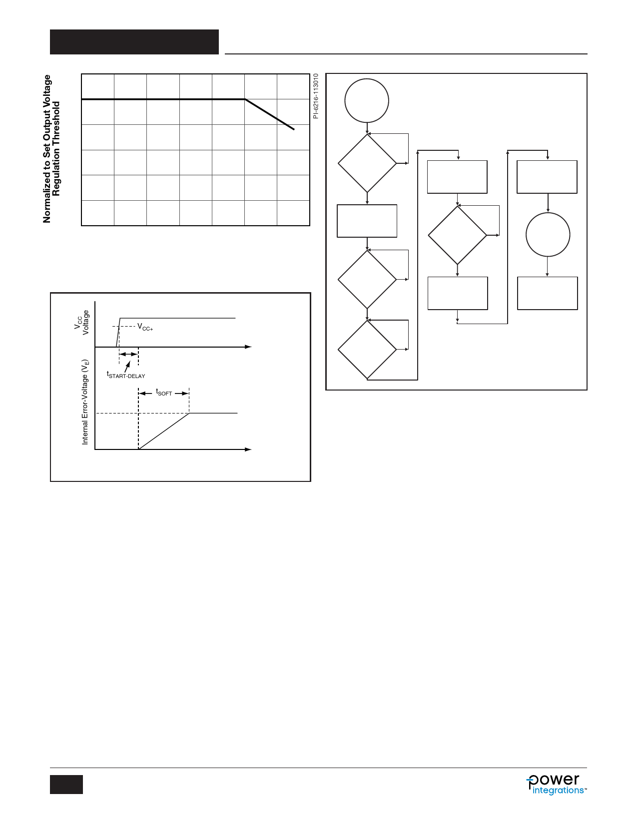
tSTART-DELAY
~5 V
tSOFT
t
PI-5336-110810
Figure 6. Power Limit Soft-Start Function.
NPN and PNP transistor are tied between the output voltage
divider resistors to limit the maximum overshoot and under-
shoot during a load transient response. To reduce switch and
output diode current stress at start-up, the HiperPFS slews the
internal error-voltage from zero to its steady-state value at
start-up. Figure 6 illustrates the relative relationship between
the application of VCC and power limit soft-start function through
the internal error-voltage.
The error-voltage has a controlled slew rate of 0.25 V/ms at
start-up, corresponding to the tSOFT time duration for a full scale
error voltage of 5 V.
The beginning of soft-start is gated by the VCC+, IUV+ and
FEEDBACK pin voltage thresholds in the sequence described
below. Once the applied VCC is above the VCC+ threshold, the
sensed V pin current is above IUV+ and the feedback pin voltage
is above FBOFF, the IC applies a ~6 mA current sink through the
VOLTAGE MONITOR pin and checks that the FEEDBACK pin
voltage is still above the FBOFF threshold. This checks to ensure
that the FEEDBACK and V pins are not shorted together. In the
event that the FEEDBACK pin voltage is below the FBOFF
YES
Figure 7. Start-Up Sequence.
PI-5337-110910
threshold the V pin holds the 6 mA current sink indefinitely until
the FEEDBACK pin is above the FBOFF. If the FEEDBACK pin
voltage is above FBOFF, the IC releases the current source and
resumes with normal soft-start and operation. Figure 7
illustrates this sequence.
Timing Supervisor and Operating Frequency Range
Since the controller is expected to operate with a variable
switching frequency over the line frequency half-cycle, typically
spanning a range of 24 – 95 kHz, the controller also features a
timing supervisor function which monitors and limits the
maximum switch on-time and off-time as well as ensures a
minimum cycle off-time. The timer supervisor limits the normal
operating frequency range for loads in excess of 10% of the
device peak power rating.
Figure 8a shows the typical half-line frequency profile of the
device switching frequency as a function of input voltage at
peak load conditions. Figure 8b shows for a given line condition
the effect of EcoSmart to the switching frequency as a function
of load (PFS704-716). The switching frequency is not a function
of boost choke inductance.
EcoSmart
The PFS704-716 controllers includes an EcoSmart mode
wherein the internal error signal (VE) is used to detect the
converter output power. Since the internal error-signal is
directly proportional to the output power, this signal level is used
to set the average switching frequency as a function of output
power. The off-time integrator control reference (VOFF) is
6
Rev. G 06/15
www.power.com
Share Link: 