RMWB24001 Ver la hoja de datos (PDF) - Raytheon Company
Número de pieza
componentes Descripción
Lista de partido
RMWB24001 Datasheet PDF : 6 Pages
| |||
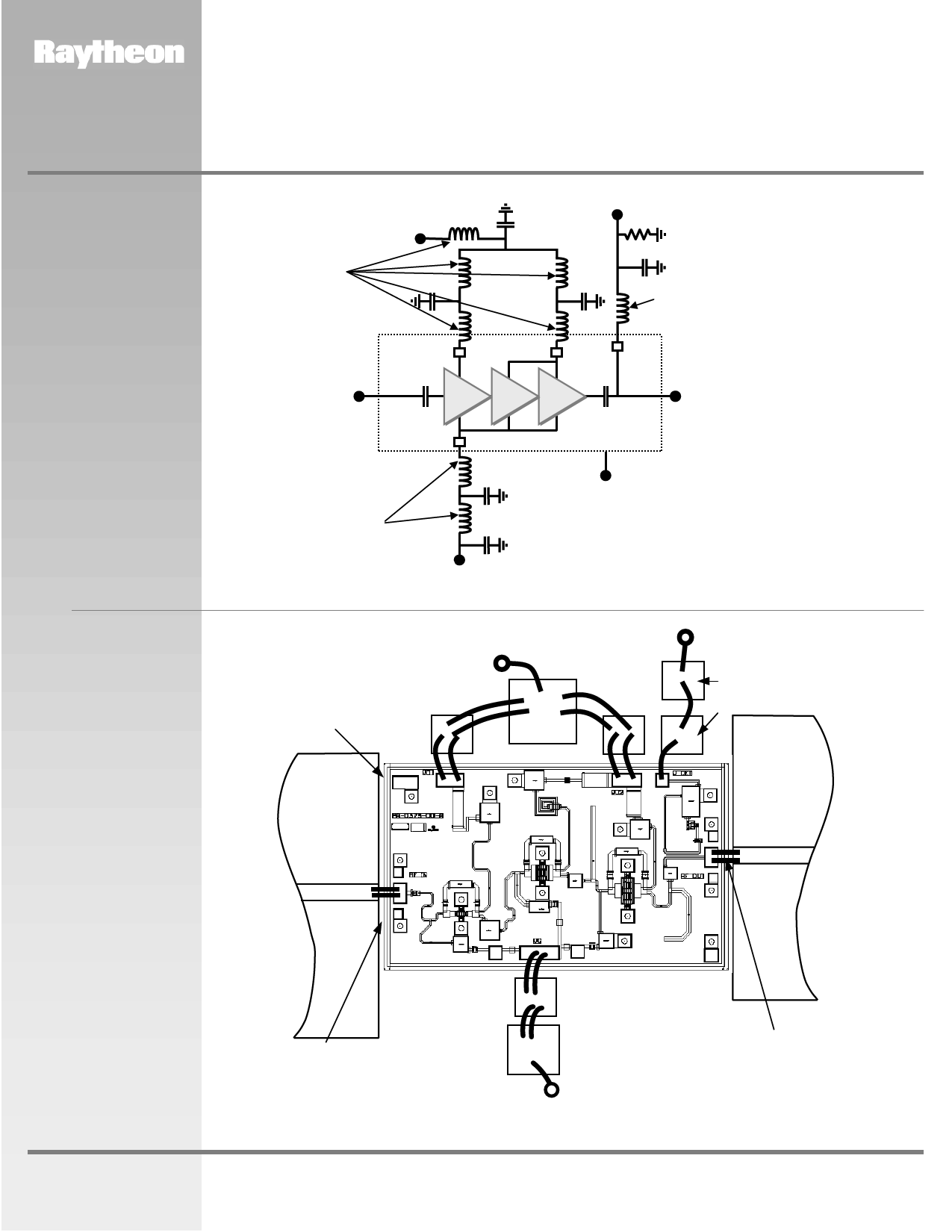
RMWB24001
24 GHz Buffer Amplifier MMIC
Figure 3
Recommended
Application Schematic
Circuit Diagram
Drain Supply
Vd=4 V
Bond Wires
100 pF
10,000 pF
Output Power
Detector Voltage Vdet
3 kΩ
100 pF
PRODUCT INFORMATION
100 pF
Bond Wires
MMIC Chip
RF IN
RF OUT
Bond Wires
100 pF
10,000 pF
Ground
(Back of Chip)
Figure 4
Recommended
Assembly Diagram
Note:
Gate Supply Vg
Detector delivers > 0.1 V DC into 3 kΩ load resistor for > +17 dBm output power. If output power level detection is not desired, do not connect to
detector bond pad.
Die-Attach
80 Au/20 Sn
Drain Supply
Vd= 4 V
10,000 pF
100 pF
5mil Thick
Alumina
50 ohms
100 pF
Output Power
Detector Voltage Vdet
3 kΩ
100 pF
5 mil Thick
Alumina
50 ohms
RF Input
RF Output
www.raytheon.com/micro
100pF
2 mil Gap
10,000pF
L< 0.015”
(4 Places)
Note:
Gate Supply Vg
Use 0.003” by 0.0005” Gold Ribbon for bonding. RF input and output bonds should be less than 0.015” long with stress relief.
Characteristic performance data and specifications are subject to change without notice.
Revised March 14, 2001
Page 3
Raytheon RF Components
362 Lowell Street
Andover, MA 01810
Share Link: 