LH540215 Ver la hoja de datos (PDF) - Sharp Electronics
Número de pieza
componentes Descripción
Lista de partido
LH540215 Datasheet PDF : 48 Pages
| |||
LH540215/25
512 x 18/1024 x 18 Synchronous FIFO
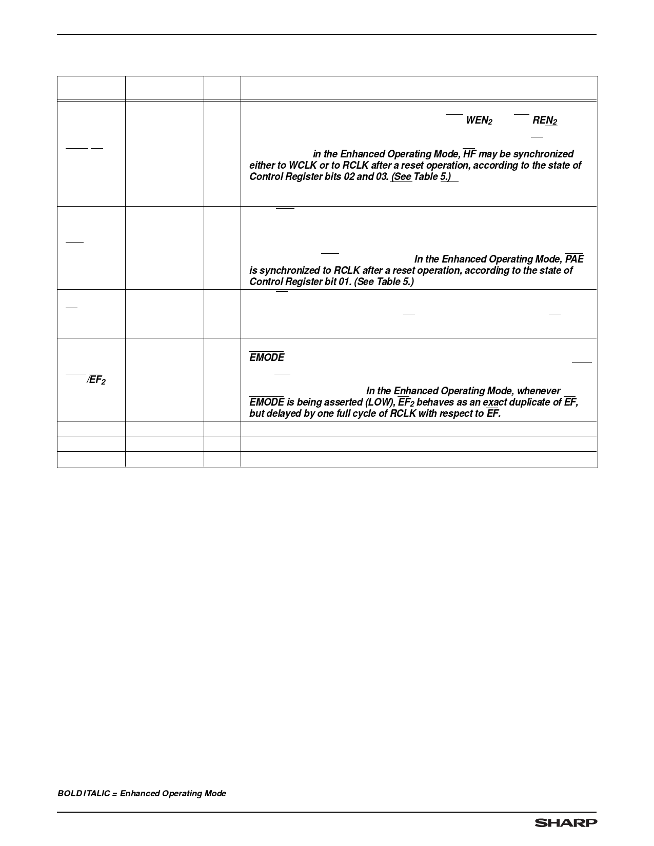
PIN DESCRIPTIONS (cont’d)
PIN
NAME
PIN
TYPE 1
DESCRIPTION
WXO/HF
Write
Expansion
Output/
Half-Full Flag
This signal is dual-purpose; its functionality is determined during a reset operation
according to the states of the two control inputs WXI/WEN2 and RXI/REN2. (See
Tables 1 and 2.) In the standalone or paralleled configuration, whenever HF is LOW
the device is more than half full. In IDT-Compatible Operating Mode, HF is
O asynchronous; in the Enhanced Operating Mode, HF may be synchronized
either to WCLK or to RCLK after a reset operation, according to the state of
Control Register bits 02 and 03. (See Table 5.) In the IDT-compatible cascaded
configuration, a pulse is sent from WXO to the WXI input of the next FIFO in the
daisy-chain cascade, whenever the last location in the FIFO is written.
When PAE is LOW, the FIFO is ‘almost empty,’ based on the almost-empty-offset
value programmed into the FIFO’s Almost-Empty Offset Register. The default value
Programmable
of this offset at reset is one-eighth of the total number of words in the FIFO-memory
PAE
Almost-Empty
O array, minus one, measured from ‘empty.’ (See Table 4.) In IDT-Compatible
Flag
Operating Mode, PAE is asynchronous. In the Enhanced Operating Mode, PAE
is synchronized to RCLK after a reset operation, according to the state of
Control Register bit 01. (See Table 5.)
When EF is LOW, the FIFO is empty; further advancement of its internal read-
EF
Empty Flag
O
address pointer, and further readout of data words from its internal memory array to
its Data Outputs, are inhibited. When EF is HIGH, the FIFO is not empty. EF is
synchronized to RCLK.
RXO/EF2
Read
Expansion
Output
This signal is dual-purpose; its functionality is determined by the state of the
EMODE control input during a reset operation. (See Tables 1 and 2.) In the IDT-
Compatible Operating Mode, in a cascaded configuration, a pulse is sent from RXO
O to the RXI input of the next FIFO in the daisy-chain cascade, whenever the last
location of the FIFO is read. In the Enhanced Operating Mode, whenever
EMODE is being asserted (LOW), EF2 behaves as an exact duplicate of EF,
but delayed by one full cycle of RCLK with respect to EF.
Q0 – Q17
VCC
VSS
Data Outputs
Power
Ground
O/Z Data outputs to drive an 18-bit bus.
V +5 V power-supply pins.
V 0 V ground pins.
NOTE:
1. I = Input, O = Output, Z = High-Impedance, V = Power Voltage Level
BOLD ITALIC = Enhanced Operating Mode
8
Share Link: 