MC74VHC244 Ver la hoja de datos (PDF) - ON Semiconductor
Número de pieza
componentes Descripción
Lista de partido
MC74VHC244 Datasheet PDF : 8 Pages
| |||
MC74VHC244
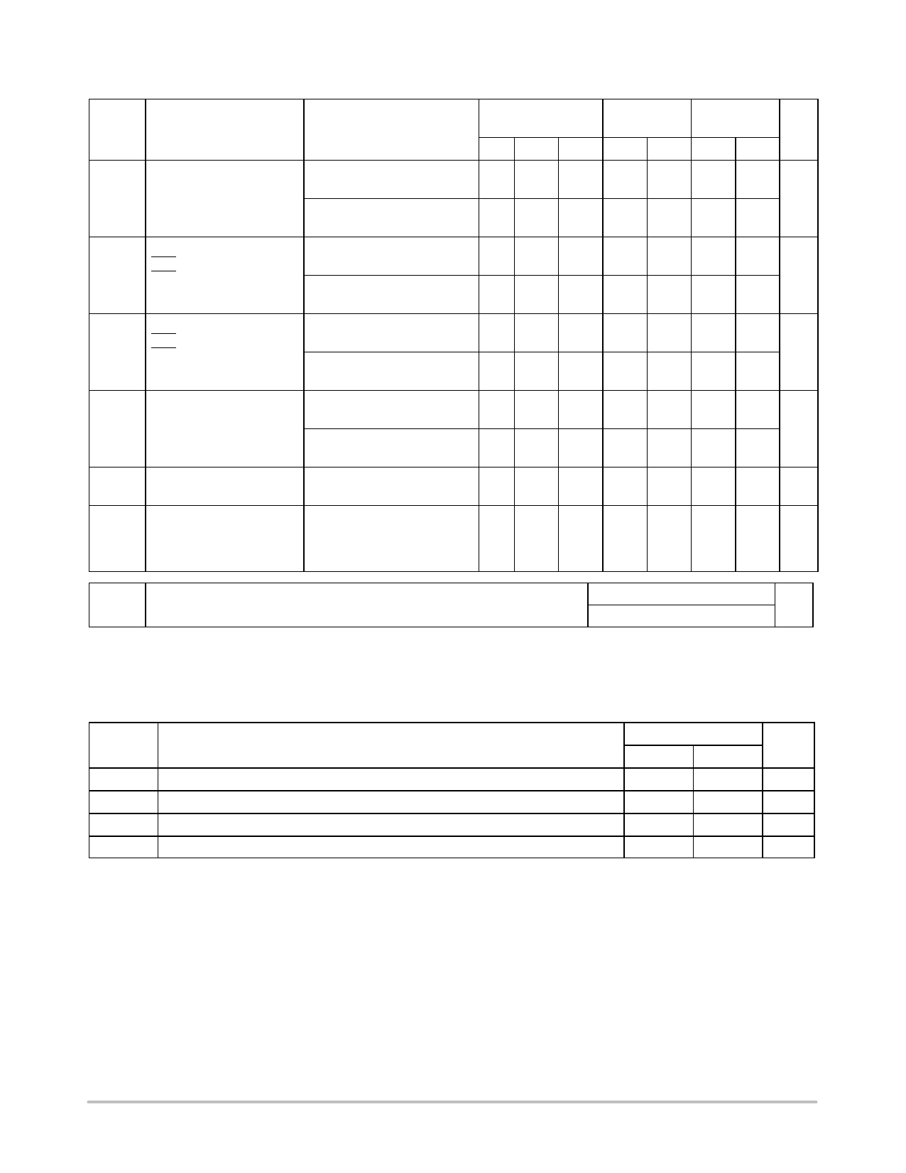
ÎÎÎÎÎÎÎÎÎÎÎÎÎÎÎÎÎÎÎÎÎÎÎÎÎÎÎÎÎÎÎÎÎ AC ELECTRICAL CHARACTERISTICS (Input tr = tf = 3.0 ns)
ÎÎÎÎÎÎÎÎÎÎÎÎÎÎÎÎÎÎÎÎÎÎÎÎÎÎÎÎÎÎÎÎÎÎÎÎÎÎÎÎÎÎÎÎÎÎÎÎÎÎÎÎÎÎÎÎÎÎÎÎÎÎÎÎÎÎ Symbol
Parameter
ÎÎÎÎÎÎÎÎÎÎÎÎÎÎÎÎÎÎÎÎÎÎÎÎÎÎÎÎÎÎÎÎÎ tPLH,
ÎÎÎÎÎÎÎÎÎÎÎÎÎÎÎÎÎÎÎÎÎÎÎÎÎÎÎÎÎÎÎÎÎÎÎÎÎÎÎÎÎÎÎÎÎÎÎÎÎÎÎÎÎÎÎÎÎÎÎÎÎÎÎÎÎÎ tPHL
Maximum Propagation
Delay, A to YA or
B to YB
ÎÎÎÎÎÎÎÎÎÎÎÎÎÎÎÎÎÎÎÎÎÎÎÎÎÎÎÎÎÎÎÎÎÎÎÎÎÎÎÎÎÎÎÎÎÎÎÎÎÎÎÎÎÎÎÎÎÎÎÎÎÎÎÎÎÎ tPZL,
ÎÎÎÎÎÎÎÎÎÎÎÎÎÎÎÎÎÎÎÎÎÎÎÎÎÎÎÎÎÎÎÎÎ tPZH
Output Enable Time
OEA to YA or
OEB to YB
ÎÎÎÎÎÎÎÎÎÎÎÎÎÎÎÎÎÎÎÎÎÎÎÎÎÎÎÎÎÎÎÎÎÎÎÎÎÎÎÎÎÎÎÎÎÎÎÎÎÎÎÎÎÎÎÎÎÎÎÎÎÎÎÎÎÎ tPLZ,
ÎÎÎÎÎÎÎÎÎÎÎÎÎÎÎÎÎÎÎÎÎÎÎÎÎÎÎÎÎÎÎÎÎ tPHZ
Output Disable Time
OEA to YA or
OEB to YB
ÎÎÎÎÎÎÎÎÎÎÎÎÎÎÎÎÎÎÎÎÎÎÎÎÎÎÎÎÎÎÎÎÎÎÎÎÎÎÎÎÎÎÎÎÎÎÎÎÎÎÎÎÎÎÎÎÎÎÎÎÎÎÎÎÎÎÎÎÎÎÎÎÎÎÎÎÎÎÎÎÎÎÎÎÎÎÎÎÎÎÎÎÎÎÎÎÎÎÎ tOSLH, OutputtoOutputSkew
ÎÎÎÎÎÎÎÎÎÎÎÎÎÎÎÎÎÎÎÎÎÎÎÎÎÎÎÎÎÎÎÎÎÎÎÎÎÎÎÎÎÎÎÎÎÎÎÎÎÎÎÎÎÎÎÎÎÎÎÎÎÎÎÎÎÎ tOSHL
TA = 25°C
Test Conditions
Min Typ Max
VCC = 3.3 ± 0.3 V CL = 15 pF
CL = 50 pF
5.8 8.4
8.3 11.9
VCC = 5.0 ± 0.5 V CL = 15 pF
CL = 50 pF
3.9 5.5
5.4 7.5
VCC = 3.3 ± 0.3 V CL = 15 pF
RL = 1 kW
CL = 50 pF
6.6 10.6
9.1 14.1
VCC = 5.0 ± 0.5 V CL = 15 pF
RL = 1 kW
CL = 50 pF
4.7 7.3
6.2 9.3
VCC = 3.3 ± 0.3 V CL = 50 pF
RL = 1 kW
10.3 14.0
VCC = 5.0 ± 0.5 V CL = 50 pF
RL = 1 kW
6.7 9.2
VCC = 3.3 ± 0.3 V CL = 50 pF
1.5
(Note 6)
VCC = 5.0 ± 0.5 V CL = 50 pF
1.0
(Note 6)
ÎÎÎÎÎÎÎÎÎÎÎÎÎÎÎÎÎÎÎÎÎÎÎÎÎÎÎÎÎÎÎÎÎ Cin MaximumInput
Capacitance
4
10
ÎÎÎÎÎÎÎÎÎÎÎÎÎÎÎÎÎÎÎÎÎÎÎÎÎÎÎÎÎÎÎÎÎÎÎÎÎÎÎÎÎÎÎÎÎÎÎÎÎÎÎÎÎÎÎÎÎÎÎÎÎÎÎÎÎÎ Cout MaximumThree−State
6
Output Capacitance
ÎÎÎÎÎÎÎÎÎÎÎÎÎÎÎÎÎÎÎÎÎÎÎÎÎÎÎÎÎÎÎÎÎ (Output in High−Impedance
ÎÎÎÎÎÎÎÎÎÎÎÎÎÎÎÎÎÎÎÎÎÎÎÎÎÎÎÎÎÎÎÎÎÎÎÎÎÎÎÎÎÎÎÎÎÎÎÎÎÎÎÎÎÎÎÎÎÎÎÎÎÎÎÎÎÎ State)
TA 3 85°C
Min Max
1.0 10.0
1.0 13.5
1.0 6.5
1.0 8.5
1.0 12.5
1.0 16.0
1.0 8.5
1.0 10.5
1.0 16.0
1.0 10.5
1.5
1.0
10
−55°C 3 TA
3 125°C
Min Max Unit
1.0 11.0 ns
1.0 14.5
1.0 7.5
1.0 9.5
1.0 13.5 ns
1.0 17.0
1.0 9.5
1.0 11.5
1.0 17.0 ns
1.0 11.5
1.5 ns
1.5
10 pF
pF
Typical @ 25°C, VCC = 5.0V
CPD Power Dissipation Capacitance (Note 7)
19
pF
6. Parameter guaranteed by design. tOSLH = |tPLHm − tPLHn|, tOSHL = |tPHLm − tPHLn|.
7. CPD is defined as the value of the internal equivalent capacitance which is calculated from the operating current consumption without load.
Average operating current can be obtained by the equation: ICC(OPR) = CPD VCC fin + ICC / 8 (per bit). CPD is used to determine the no−load
dynamic power consumption; PD = CPD VCC2 fin + ICC VCC.
NOISE CHARACTERISTICS (Input tr = tf = 3.0 ns, CL = 50 pF, VCC = 5.0 V)
Symbol
VOLP
VOLV
VIHD
VILD
Parameter
Quiet Output Maximum Dynamic VOL
Quiet Output Minimum Dynamic VOL
Minimum High Level Dynamic Input Voltage
Maximum Low Level Dynamic Input Voltage
TA = 25°C
Typ
Max
Unit
0.6
0.9
V
−0.6
−0.9
V
3.5
V
1.5
V
http://onsemi.com
4
Share Link: 