MT9041 Ver la hoja de datos (PDF) - Mitel Networks
Número de pieza
componentes Descripción
Lista de partido
MT9041 Datasheet PDF : 14 Pages
| |||
Advance Information
MT9041
Freerun Accuracy
Jitter Transfer Function
The Freerun accuracy of the PLL is a measure of
how accurately the PLL can reproduce the desired
output frequency. The freerun accuracy is a function
of master clock frequency which must be 20 MHz
±32 ppm in order to meet AT & T TR62411 and ETSI
specifications.
Jitter Performance
The output jitter of a digital trunk PLL is composed of
intrinsic jitter, measured using a jitter free reference
clock, and frequency dependent jitter, measured by
applying known levels of jitter on the references
clock. The jitter spectrum indicates the frequency
content of the output jitter.
Intrinsic Jitter
Intrinsic jitter is the jitter added to an output signal by
the processing device, in this case the enhanced
PLL. Tables 3 and 4 show the average measured
intrinsic jitter of the T1 and E1 outputs. Each
measurement is an average based upon a ±100 ppm
deviation (in steps of 20 ppm) on the input reference
clock. Jitter on the master clock will increase intrinsic
jitter of the device, hence attention to minimization of
master clock jitter is required.
The jitter transfer function is a measure of the
transfer characteristics of the PLL to frequency
specific jitter on the referenced input of the PLL. It is
directly linked to the loop bandwidth and the
magnitude of the phase error suppression
characteristics of the PLL. It is measured by applying
jitter of specific magnitude and frequencies to the
input of the PLL, then measuring the magnitude of
the output jitter (both filtered and unfiltered) on the
T1 or E1 output.
Care must be taken when measuring the transfer
characteristics to ensure that critical jitter alias
frequencies are included in the measurement (i.e.,
for digital phase locked loops using an 8 kHz input).
Tables 5 and 6 provide measured results for the jitter
transfer characteristics of the PLL for both a 1.544
MHz and 2.048 MHz reference input clock. The
transfer characteristics for an 8 kHz reference input
will be the same.
Figures 4 and 5 show the jitter attenuation
performance of the T1 and E1 outputs plotted
against AT & T TR62411 and ETSI requirements,
respectively.
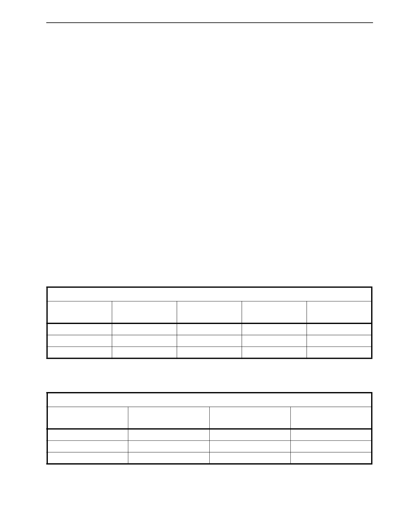
Output Jitter in UIp-p
Reference Input
FLT0 Unfiltered
FLT1
10Hz - 8kHz
FLT2
10Hz - 40kHz
FLT3
8kHz - 40kHz
8 kHz
.011
.004
.006
.002
1.544 MHz
.011
.001
.002
.001
2.048 MHz
.011
.001
.002
.001
Table 3 -Typical Intrinsic Jitter for the T1 Output
Typical figures are at 25°C and are for design aid only: not guaranteed and not subject to production testing.
Output Jitter in UIp-p
Reference Input
FLT0 Unfiltered
FLT1
20Hz - 100kHz
FLT2
700Hz - 100kHz
8 kHz
.011
.002
.002
1.544 MHz
.011
.002
.002
2.048 MHz
.011
.002
.002
Table 4 - Typical Intrinsic Jitter for the E1 Output
Typical figures are at 25°C and are for design aid only: not guaranteed and not subject to production testing.
3-87
Share Link: 