PCF8584 Ver la hoja de datos (PDF) - NXP Semiconductors.
Número de pieza
componentes Descripción
Lista de partido
PCF8584 Datasheet PDF : 40 Pages
| |||
Philips Semiconductors
I2C-bus controller
Product specification
PCF8584
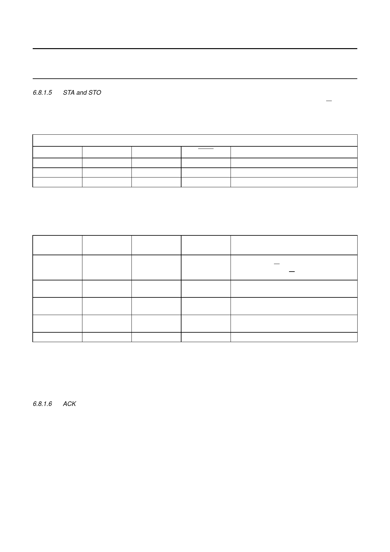
6.8.1.5 STA and STO
These bits control the generation of the I2C-bus START condition and transmission of slave address and R/W bit,
generation of repeated START condition, and generation of the STOP condition (see Table 7).
Table 6 Register access control; ESO = 1 (serial interface on) and ES1 = 1; long-distance (4-wire) mode; note 1
INTERNAL REGISTER ADDRESSING: LONG-DISTANCE (4-WIRE) MODE
A0
ES1
ES2
IACK
FUNCTION
1
1
X
1
W S1: control
1
1
X
X
R S1; status
0
1
X
X
R/W S0; (data)
Note
1. Trying to read from or write to registers other than S0 and S1 (setting ESO = 0) brings the PCF8584 out of the
long-distance mode.
Table 7 Instruction table for serial bus control
STA
STO
PRESENT
MODE
FUNCTION
OPERATION
1
0
SLV/REC
START
transmit START + address, remain
MST/TRM if R/W = 0;
go to MST/REC if R/W = 1
1
0
MST/TRM
REPEAT same as for SLV/REC
START
0
1
MST/REC;
STOP READ; transmit STOP go to SLV/REC mode; note 1
MST/TRM
STOP WRITE
1
1
MST
DATA
send STOP, START and address after last
CHAINING master frame without STOP sent; note 2
0
0
ANY
NOP
no operation; note 3
Notes
1. In master receiver mode, the last byte must be terminated with ACK bit HIGH (‘negative acknowledge’).
2. If both STA and STO are set HIGH simultaneously in master mode, a STOP condition followed by a START
condition + address will be generated. This allows ‘chaining’ of transmissions without relinquishing bus control.
3. All other STA and STO mode combinations not mentioned in Table 7 are NOPs.
6.8.1.6 ACK
This bit must be set normally to a logic 1. This causes the I2C-bus controller to send an acknowledge automatically after
each byte (this occurs during the 9th clock pulse). The bit must be reset (to logic 0) when the I2C-bus controller is
operating in master/receiver mode and requires no further data to be sent from the slave transmitter. This causes a
negative acknowledge on the I2C-bus, which halts further transmission from the slave device.
6.8.2 REGISTER S1 STATUS SECTION
The read-only section of S1 enables access to I2C-bus status information; see Table 4.
1997 Oct 21
11
Share Link: 