PCF8584 Ver la hoja de datos (PDF) - NXP Semiconductors.
Número de pieza
componentes Descripción
Lista de partido
PCF8584 Datasheet PDF : 40 Pages
| |||
Philips Semiconductors
I2C-bus controller
Product specification
PCF8584
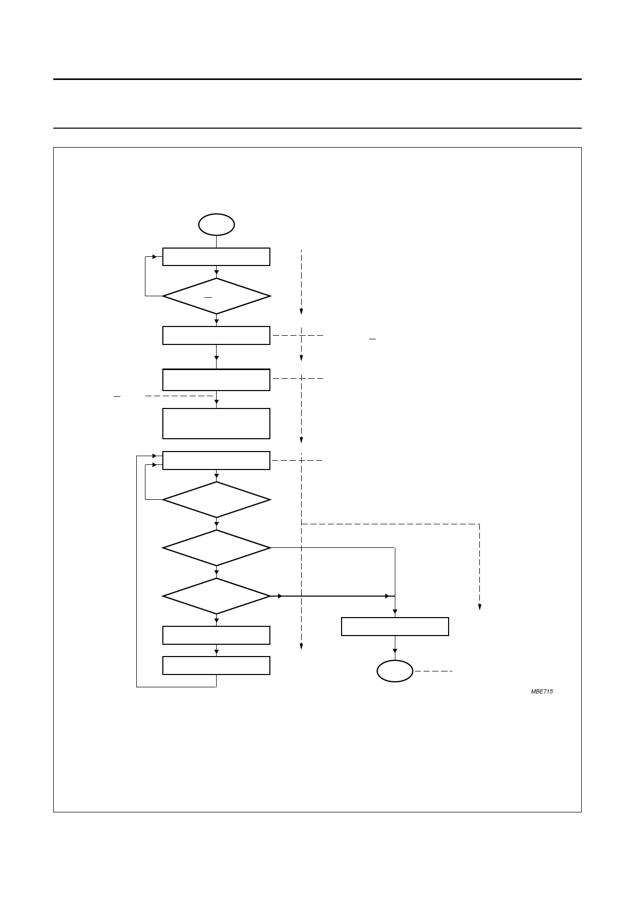
handbook, full pagewidth
START
read byte from S1 register
A0 = HIGH
is bus busy?
yes
(BB = 0?)
no
send byte 'slave address'
PCF8584 remains in
master transmitter
mode if R/W bit of
'slave address' = 0
send C5H to control
register S1
n = 0 (data byte counter);
m = number of data bytes
to be transferred
read byte from S1 register
A0 = LOW
Load 'slave address' into S0 register:
'slave address' = value of slave address
(7-bits + R/W = 0). After reset, default = '0'
A0 = HIGH
Load C5H into S1. 'C5H' = PCF8584 generates
the 'START' condition and clocks out the slave
address and the clock pulse for slave acknowledgement.
Next byte(s) sent to the S0 register will be immediately
transferred over the I2C-bus.
A0 = HIGH
Poll for transmission finished.
PIN bit = 0?
no
yes
slave
acknowledged?
(LRB = 0?)
yes
n=m
yes
no
n=n+1
transmission
completed
send byte C3H
send byte 'data'
A0 = LOW
Load 'data'
into bus
buffer register S0;
data is transmitted.
END
A0 = HIGH
Load C3 into the S1 control
register: PCF8584 generates
'STOP' condition.
PCF8584 goes into
slave receiver mode
MBE715
1997 Oct 21
Fig.6 PCF8584 master transmitter mode.
16
Share Link: 