SM8135B Ver la hoja de datos (PDF) - Nippon Precision Circuits
Número de pieza
componentes Descripción
Lista de partido
SM8135B Datasheet PDF : 19 Pages
| |||
SM8135B
VOUT Output Circuit Mode Switching
The SM8135B output mode switches between 4 operating modes in response to the operating conditions. The
modes are: standby mode, ×1.0 mode (VIN through mode), ×1.5 mode (1.5-times charge pump boost), and
×2.0 mode (2.0-times charge pump boost). Specifically, the use of ×1.0 mode, ×1.5 mode, and ×2.0 mode
allows the VOUT output to be adjusted automatically to match drive LED characteristics. Switching between
×1.0 mode, ×1.5 mode, and ×2.0 mode is controlled automatically by an internal circuit. The operating mode
cannot be specified by an external control signal.
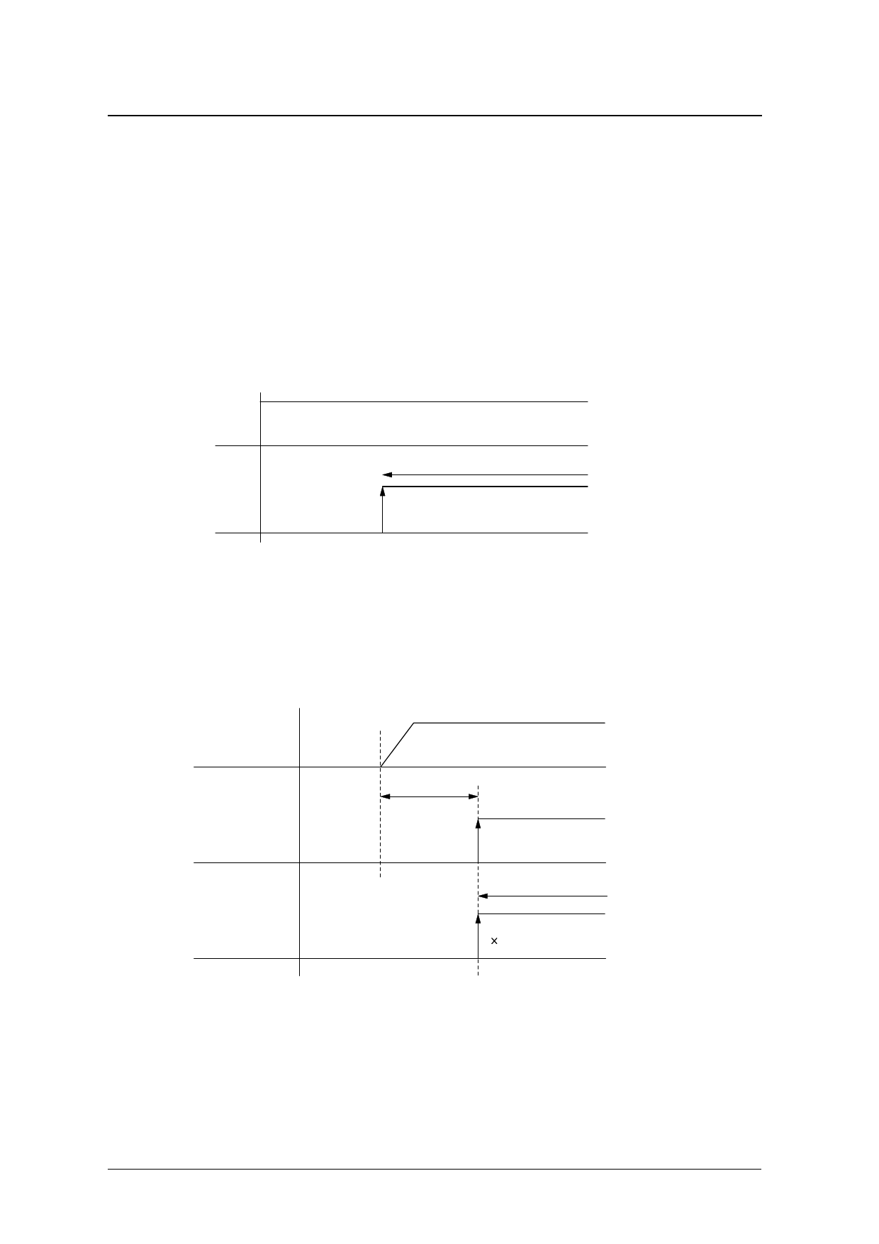
Startup: Internal Reset Time and Soft Start Time
The SM8135B normal startup procedure (after VIN has been applied previously) is to switch from standby
mode to the ×1.0/×1.5/×2.0 operating modes when the EN enable input goes HIGH. The soft start time
(described on the following page) begins after switching to the operating mode using EN.
VIN High
VIN
EN Standby mode
(1)
Soft start time
ENABLE ON
(2)
Normal startup
(1) VIN is HIGH, EN is LOW (standby mode)
(2) Switches to an operating mode when EN goes HIGH (soft start time begins)
If the VIN supply voltage is applied when EN is HIGH level, startup commences after the power-ON reset
(POR) time (approximately 50µs) has elapsed.
VIN power source
(1)
Internal
power on
reset
Internal
enable
(CE)
POR time
typ: 50µs
(2)
Standby mode
Soft start time
(3)
1.5 mode
Internal reset operation when power is applied (power-ON reset)
(1) VIN voltage rises when power is applied.
(2) Power-ON reset (POR) circuit resets internal circuits approximately 50µs after the power is applied.
(3) If EN is HIGH when power is applied, the internal circuits start operating when the internal “CE” signal ris-
ing edge occurs after the power-ON reset time. If EN is LOW when power is applied, the “CE” rising edge
occurs simultaneously with the first rising edge.
SEIKO NPC CORPORATION —7
Share Link: 