CS5317 Ver la hoja de datos (PDF) - Cirrus Logic
Número de pieza
componentes Descripción
Lista de partido
CS5317 Datasheet PDF : 32 Pages
| |||
CS5317
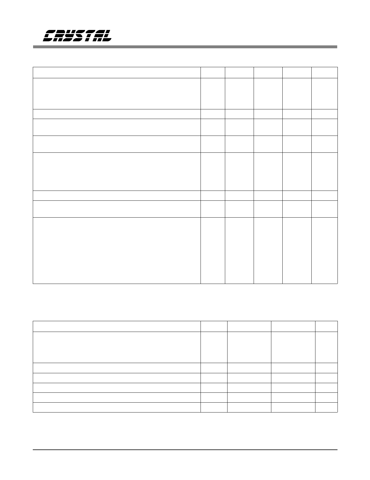
SWITCHING CHARACTERISTICS (TA = TMIN-TMAX; CL=50 pF; VD+ = 5V±10%; VD- = -5V±10%)
Parameter
Symbol Min
Typ
Max Units
Master Clock Frequency:
CLKIN
CLKG1 Mode
CLKG2 Mode
CLKOR Mode
fclkg1
-
fclkg2
-
fclkor
-
Output Word Rate:
DOUT
fdout
-
Rise Times:
Any Digital Input
Any Digital Output
trisein
-
triseout
-
Fall Times:
Any Digital Input
Any Digital Output
tfallin
-
tfallout
-
CLKIN Duty Cycle
CLKG1 and CKLG2 Modes
CLKOR Mode
Pulse Width Low tpwl1
200
Pulse Width High tpwh1
200
Pulse Width Low tpwl1
45
Pulse Width High tpwh1
45
RST Pulse Width Low
tpwr
400
Set Up Times:
RST High to CLKIN High
CLKIN High to RST High
tsu1
40
tsu2
40
Propagation Delays:
DOE Falling to Data Valid
CLKIN Rising to DOUT Falling
DOE Rising to Hi-Z Output
CLKOUT Rising to DOUT Falling
CLKOUT Rising to DOUT Rising
CLKOUT Rising to Data Valid
CLKIN Rising to CLKOUT Falling
CLKIN Rising to CLKOUT Rising
tphl1
-
(Note 11) tphl2
-
tplh1
-
tplh2
-
tplh3
-
tplh4
-
(Note 12) tplh5
-
(Note 12) tplh6
-
Notes: 11. CLKIN only pertains to CLKG1 and CLKG2 modes.
12. Only valid in CLKOR mode.
-
20
kHz
-
10
kHz
-
5.12
MHz
-
20
kHz
20
1000
ns
15
20
ns
20
1000
ns
15
20
ns
-
-
ns
-
-
ns
-
-
ns
-
-
ns
-
-
ns
-
-
ns
-
-
ns
-
150
ns
1
- CLKOUT
-
80
cycles
-
60
ns
-
60
ns
-
100
ns
-
200
ns
-
200
ns
ABSOLUTE MAXIMUM RATINGS (DGND, AGND = 0V, all voltages with repect to groung)
Parameter
Symbol
Min
Max
Units
DC Power Supplies:
Positive Digital
Negative Digital
Positive Analog
Negative Analog
VD+
VD-
VA+
VA-
-0.3
(VA+) + 0.3 V
0.3
-6.0
V
-0.3
6.0
V
0.3
-6.0
V
Input Current, Any Pin Except Supplies
(Note 13) Iin
-
±10
mA
Analog Input Voltage (AIN and VREF pins)
VINA
(VA-) - 0.3 (VA+) + 0.3
V
Digital Input Voltage
VIND
-0.3
(VD+) + 0.3 V
Ambient Operating Temperature
TA
-55
125
°C
Storage Temperature
Tstg
-65
150
°C
Notes: 13. Transient currents up to 100mA will not cause SCR latch-up.
WARNING:Operating this device at or beyond these extremes may result in permanent damage to the device.
Normal operation of the part is not guaranteed at these extremes.
4
DS27F4
Share Link: 