CS5317 Ver la hoja de datos (PDF) - Cirrus Logic
Número de pieza
componentes Descripción
Lista de partido
CS5317 Datasheet PDF : 32 Pages
| |||
CS5317
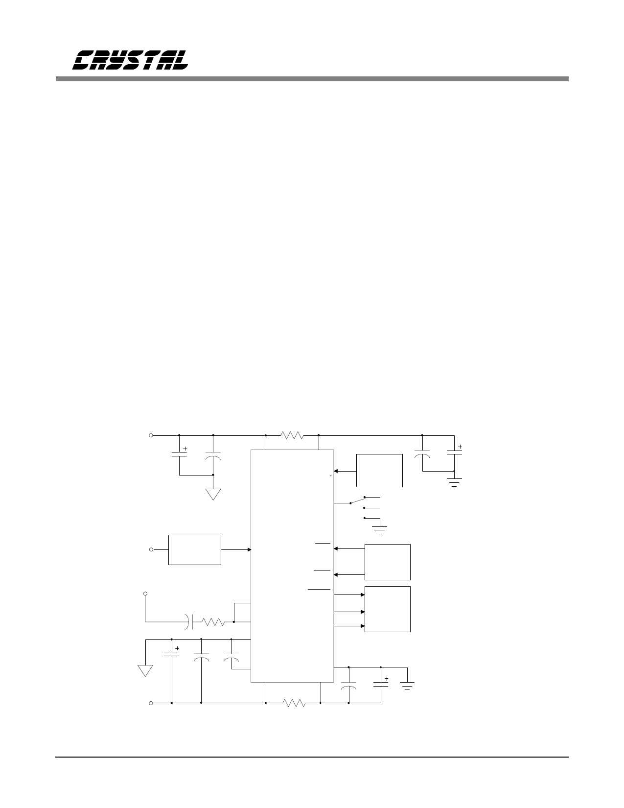
SYSTEM DESIGN WITH THE CS5317
Like a tracking ADC, the CS5317 continuously
samples and converts, always tracking the analog
input signal and updating its output register at a
20 kHz rate. The device can be read at any rate to
create any system-level sampling rate desired up
to 20kHz.
Clocking
Oversampling is a critical function in delta-sigma
A/D conversion. Although system-level output
sample rates typically remain between 7kHz and
20kHz in voiceband applications, the CS5317 ac-
tually samples and converts the analog input at
rates up to 2.56 MHz. This internal sampling rate
is typically set by a master clock which is on the
order of several megahertz. See Table1 for a com-
plete description of the clock relationships in the
various CS5317 operating modes.
Some systems such as echo-canceling modems,
though, require the output sampling rate to be
locked to a sampling signal which is 20 kHz or
below. For this reason the CS5317 includes an
on-chip phase-lock loop (PLL) which can gener-
ate its requisite 5.12 MHz master clock from a
20 kHz sampling signal.
The CS5317 features two modes of operation
which utilize the internal PLL. The first, termed
Clock Generation 1 (CLKG1), accepts a sam-
pling clock up to 20 kHz at the CLKIN pin and
internally generates the requisite 5.12 MHz clock.
The CS5317 then processes samples updating its
output register at the rate defined at CLKIN, typi-
cally 20 kHz. For a 20 kHz clock input the digital
filter’s 3 dB corner is set at 5.239 kHz, so CLKG1
provides a factor of 2X oversampling at the sys-
tem level (20 kHz is twice the minimum possible
sampling frequency needed to reconstruct a 5
kHz input). The CLKG1 mode is initiated by ty-
ing the MODE input to +5V.
+5V
Analog
Supply
10 µF
0.1 µF
10 Ω
1
VA+
2
VD+
9
CLKIN
Clock
Source
0.1 µF
10 µF
Analog
Signal
Source
VA+
-5V
Analog
Supply
MODE 7
CS5317
VD- (clock override mode / CLKOR)
VD+ (clock gen. mode / CLKG1)
(clock gen. mode / CLKG2)
Signal
Conditioning
11 AIN
± 2.75V
16
RST
3
DOE
uP or DSP
Control
25 nF
25 kΩ
18
VCOIN
17
PHDT
15 AGND
0.1 µF 0.1 µF
DOUT 8
6
DATA
5
CLKOUT
Serial
Data
Interface
10 µF
12
REFBUF
VA-
4
DGND
VD-
14
10 Ω
10
0.1 µF
10 µF
Figure 1. System Connection Diagram with Example PLL Components
DS27F4
7
Share Link: 