LT1680 Ver la hoja de datos (PDF) - Linear Technology
Número de pieza
componentes Descripción
Lista de partido
LT1680 Datasheet PDF : 16 Pages
| |||
LT1680
APPLICATIONS INFORMATION
ments. Generally, the selection of inductor value can be
reduced to desired maximum ripple current in the inductor
(∆I). For a boost converter, the minimum inductor value
for a given operating ripple current can be determined
using the following relation:
( ()( )( )) LMIN
=
VIN
∆I
VOUT – VIN
fO VOUT
Given an inductor value (L), the peak inductor current is
the sum of the average inductor current (IAVG) and half the
inductor ripple current (∆I), or:
( )(()( )( )) IPK
= IAVG
+
VIN VOUT
2 L fO
– VIN
VOUT
The inductor core type is determined by peak current and
efficiency requirements. The inductor core must with-
stand this peak current without saturating, and the series
winding resistance and core losses should be kept as
small as is practical to maximize conversion efficiency.
The LT1680 peak current threshold is 40% greater than
the average limit threshold. Slope compensation effects
reduce this margin as duty cycle increases. This margin
must be maintained to prevent peak current limit from
corrupting the programmed value for average current
limit. Programming the peak ripple current to less than
15% of the desired average current limit value will assure
proper operation of the average current limit feature
through 90% duty cycle (see Slope Compensation).
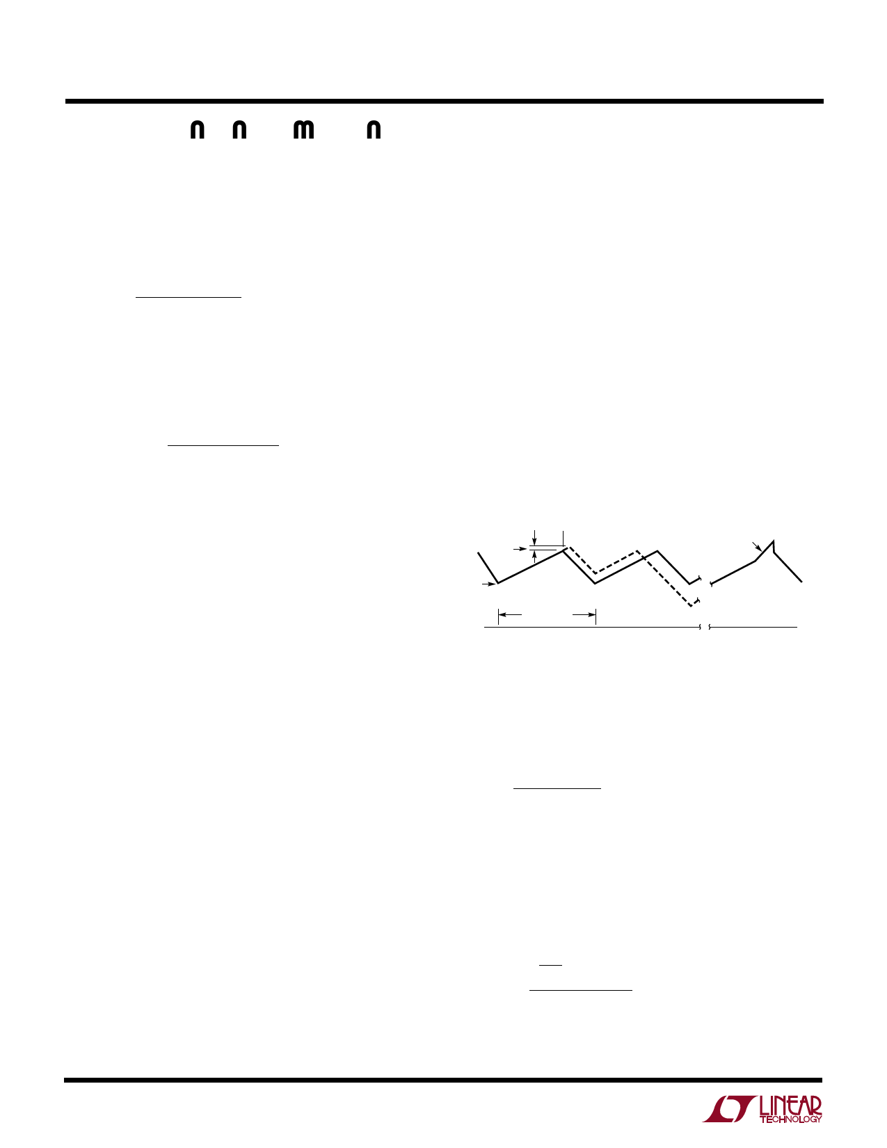
Slope Compensation
Current mode switching regulators that operate with a
duty cycle greater than 50% and have continuous inductor
current can exhibit duty cycle instability. While a regulator
will not be damaged and may even continue to function
acceptably during this type of subharmonic oscillation, an
irritating high-pitched squeal is usually produced.
The criterion for current mode duty cycle instability is
met when the increasing slope of the inductor ripple
current is less than the decreasing slope, which is the
case at duty cycles greater than 50%. This condition is
illustrated in Figure 9a. The inductor ripple current starts
at I1, the beginning of each oscillator switch cycle.
Current increases at a rate S1 until the current reaches
the control trip level I2. The controller servo loop then
disables the switch and inductor current begins to de-
crease at a rate S2. If the current switch point (I2) is
perturbed slightly and increased by ∆I, the cycle time
ends such that the minimum current point is increased by
a factor of 1 + (S2/S1) to start the next cycle. On each
successive cycle, this error is multiplied by a factor of S2/
S1. Therefore, if S2/S1 is ≥ 1, the system is unstable.
Subharmonic oscillations can be eliminated by augment-
ing the increasing ripple current slope (S1) in the control
loop. This is accomplished by adding an artificial ramp on
the inductor current waveform internal to the IC (with a
slope SX) as shown in Figure 9b. If the sum of the slopes
S1 + SX is greater than S2, this condition for subharmonic
oscillation no longer exists.
∆I T1
I2
S1 + SX
I1
S1
S2
S1
S2
OSCILLATOR
PERIOD
0
a
TIME
0
b
1680 F09
Figure 9. Inductor Current at DC > 50% and
Slope Compensation Adjusted Signal
For boost topologies, the required additional current wave-
form slope, or “Slope Compensation,” follows the relation:
(S1)(2DC – 1)
( ) SX ≥ 1– DC
For duty cycles less than 50% (DC < 0.5), SX is negative and
is not required. For duty cycles greater than 50%, SX takes
on values dependent on S1 and duty cycle. S1 is simply VIN/
L. This leads to a minimum inductance requirement for a
given VIN, duty cycle and slope compensation (SX) of:
LMIN
=
VIN
SX
(2DC
1– DC
–
1)
The LT1680 contains an internal slope compensation
ramp that has an equivalent current referred value of:
12
Share Link: 