82C55A_15 Ver la hoja de datos (PDF) - Intersil
Número de pieza
componentes Descripción
Lista de partido
82C55A_15 Datasheet PDF : 30 Pages
| |||
82C55A
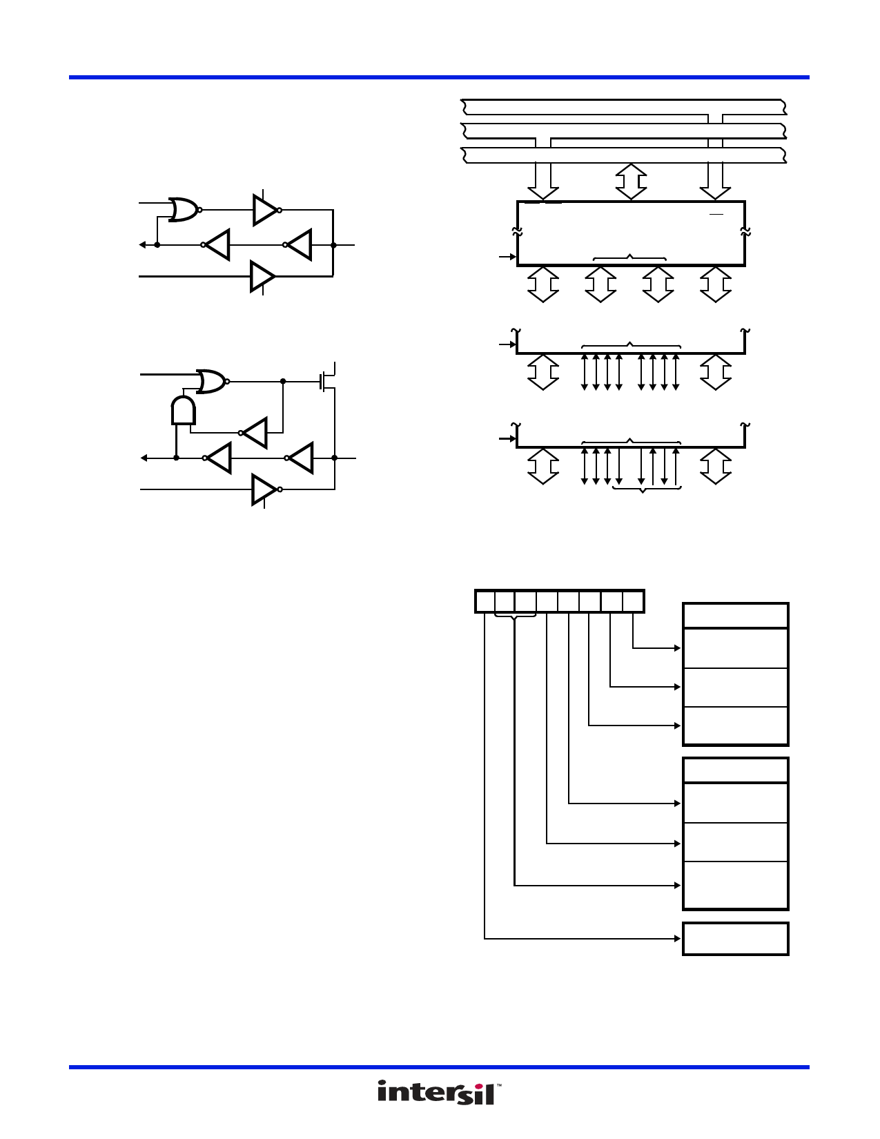
two 4-bit ports under the mode control. Each 4-bit port contains
a 4-bit latch and it can be used for the control signal output and
status signal inputs in conjunction with ports A and B. See
Figure 2B.
MASTER
RESET
OR MODE
CHANGE
INTERNAL
DATA IN
INTERNAL
DATA OUT
(LATCHED)
INPUT MODE
EXTERNAL
PORT A PIN
OUTPUT MODE
FIGURE 2A. PORT A BUS-HOLD CONFIGURATION
RESET
OR MODE
CHANGE
VCC
P
INTERNAL
DATA IN
INTERNAL
DATA OUT
(LATCHED)
EXTERNAL
PORT B, C
PIN
OUTPUT MODE
FIGURE 2B. PORT B AND C BUS-HOLD CONFIGURATION
FIGURE 2. BUS-HOLD CONFIGURATION
Operational Description
Mode Selection
There are three basic modes of operation than can be selected
by the system software:
Mode 0 - Basic Input/Output
Mode 1 - Strobed Input/Output
Mode 2 - Bidirectional Bus
When the reset input goes “high”, all ports will be set to the
input mode with all 24 port lines held at a logic “one” level by
internal bus hold devices. After the reset is removed, the
82C55A can remain in the input mode with no additional
initialization required. This eliminates the need to pull-up or
pull-down resistors in all-CMOS designs. The control word
register will contain 9Bh. During the execution of the system
program, any of the other modes may be selected using a
single output instruction. This allows a single 82C55A to
service a variety of peripheral devices with a simple software
maintenance routine. Any port programmed as an output port
is initialized to all zeros when the control word is written.
ADDRESS BUS
CONTROL BUS
DATA BUS
RD, WR
MODE 0
B
D7-D0
82C55A
C
A0-A1
CS
A
8 I/O 4 I/O 4 I/O 8 I/O
PB7-PB0 PC3-PC0 PC7-PC4 PA7-PA0
MODE 1
C
B
A
8 I/O
8 I/O
MODE 2
PB7-PB0 CONTROL CONTROL PA7-PA0
OR I/O OR I/O
B
C
8 I/O
A
BI-
DIRECTIONAL
PB7-PB0
CONTROL
PA7-PA0
FIGURE 3. BASIC MODE DEFINITIONS AND BUS INTERFACE
CONTROL WORD
D7 D6 D5 D4 D3 D2 D1 D0
GROUP B
PORT C (LOWER)
1 = INPUT
0 = OUTPUT
PORT B
1 = INPUT
0 = OUTPUT
MODE SELECTION
0 = MODE 0
1 = MODE 1
GROUP A
PORT C (UPPER)
1 = INPUT
0 = OUTPUT
PORT A
1 = INPUT
0 = OUTPUT
MODE SELECTION
00 = MODE 0
01 = MODE 1
1X = MODE 2
MODE SET FLAG
1 = ACTIVE
FIGURE 4. MODE DEFINITION FORMAT
FN2969 Rev 11.00
Dec 8, 2015
Page 5 of 30
Share Link: 