IMIC9835 Ver la hoja de datos (PDF) - Cypress Semiconductor
Número de pieza
componentes Descripción
Lista de partido
IMIC9835
Cypress Semiconductor

IMIC9835 Datasheet PDF : 18 Pages
| |||
C9835
Byte 4: VCH Clock Register (1 = Enable, 0 = Disable)
Bit @Pup[17] Pin#[18]
Description
7
0
VCH_CLK SSC Mode Enable
36 “0” = 48 MHZ (non-SSCG)
“1” = 66.6 MHz (SSCG applicable when Byte 0,Bit3 = 1)
6
0
–
Reserved. Set to 0
5
0
–
Reserved. Set to 0
4
0
–
Reserved. Set to 0
3
0
–
Reserved. Set to 0
2
0
–
Reserved. Set to 0
1
0
–
Reserved. Set to 0
0
0
–
Reserved. Set to 0
Byte 5: SSCG Control Register (1 = Enable, 0 = Disable)
Bit @Pup[17] Pin#[18]
Description
7
0
–
Spread Mode (0 = down, 1 = center)
6
0
–
Selects spread bandwidth. See Table 5.
5
0
4
0
–
Selects spread bandwidth. See Table 5.
–
Reserved. Set to 0
3
0
–
Reserved. Set to 0
2
0
–
Reserved. Set to 0
1
0
–
ESEL1 Expanded Freq. Selection MSB, See Table 2.
0
0
–
ESEL0 Expanded Freq. Selection LSB, See Table 2.
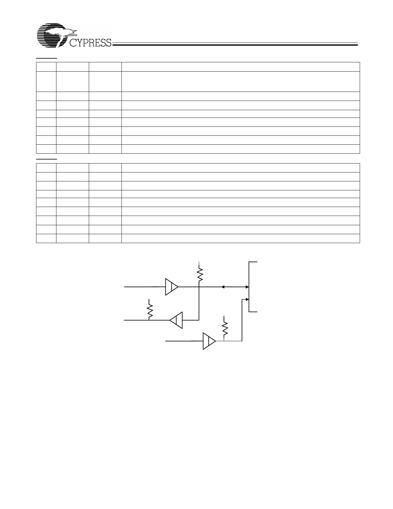
SMBus Test Circuitry
+ 5V
2.2 K
Device under
DATAIN
DATAOU
+ 5V
2.2 K
SDATA
SCLK
+ 5V
2.2 K
CLOCK
Figure 6. SMBUS Test Circuitry[19]
Spread Spectrum Clock Generation (SSCG)
Spread Spectrum is a modulation technique applied here for
maximum efficiency in minimizing EMI radiation generated by
repetitive digital signals, mainly clocks. A clock accumulates
EM energy at the center frequency it is generating. Spread
Spectrum distributes this energy over a small frequency
bandwidth therefore distributing an even amount of energy
over a wider spectrum. This technique is achieved by
modulating the clock either down or around the center (see
Figure 7 below) of its resting frequency by a certain
percentage (which also determines the energy distribution
bandwidth). In this device, Spread Spectrum is enabled by
setting SMBUS Byte0,Bit3 = 1. The default of the device at
Notes:
17. The @Pup column gives the default state at power-up
18. The Pin# column lists the relevant pin number where applicable.
power up keeps the Spread Spectrum disabled, it is therefore,
important to have SMBUS accessibility to turn-on the Spread
Spectrum function. Once the Spread Spectrum is enabled, the
spread bandwidth option is selected by SST(0:2) in SMBUS
Byte 5, bits 5, 6, and 7 . See Table 7 below.
In Down Spread mode the center frequency is shifted down
from its rested (non-spread) value by ½ of the total spread %
(e.g., assuming the center frequency is 100 MHz in
non-spread mode; when down spread of –0.5% is enabled,
the center frequency shifts to 99.75 MHz.). In Center Spread
Mode, the center frequency remains the same as in
non-spread mode.
Document #: 38-07303 Rev. **
Page 9 of 18
Share Link: