ML7012-06 Ver la hoja de datos (PDF) - LAPIS Semiconductor Co., Ltd.
Número de pieza
componentes Descripción
Lista de partido
ML7012-06 Datasheet PDF : 23 Pages
| |||
FEDL7012-06-02
ML7012-06
Analog Interface
Symbol
AOUT
RCI
RCAO
TXAI
TXAN
TXAP
AIN
GSR
SG
Type
O
I
O
I
O
O
I
O
O
Description
Transmit analog output pin
When PDN/RST = “0”, AOUT is in a high impedance state.
Operational amplifier input pin constituting transmit RC active
Operational amplifier output pin constituting transmit RC active
When PDN/RST = “0”, RCAO is in a high impedance state.
Input pin of the first line transformer drive amplifier
Output pin of the first line transformer drive amplifier
When PDN/RST = “0”, TXAN is in a high impedance state.
Output pin of the second line transformer drive amplifier
Outputs the inverted signal of TXAN
When PDN/RST = “0”, TXAP is in a high impedance state.
Input pin of the receive input amplifier
Output pin of the receive input amplifier
When PDN/RST = “0”, GSR is in a high impedance state.
Output of internal signal ground circuited
Connect to GNDA through 1F capacitor.
When PDN/RST = “0”, SG is in a high impedance state.
PSTN Line Control Interface
Symbol
RLY1
RLY2
RII
SPK
Type
O
O
I
O
Description
Output pin of signals to control off-hook and dial pulses. (*1)
“0” : On-hook or break state of dial pulse, “1” : Off-hook or make state of dial pulse
When PDN/RST = “0”, this pin outputs “0”.
Output pin of signals to control a connection to a parallelly connected telephone. (*1)
“0” : phone line is connected to the parallelly connected phone
“1” : phone line is connected to the modem (the parallelly connected phone is disconnected from
the phone line)
When PDN/RST = “0”, this pin outputs “0”.
Call-in state input pin. (*2)
Input “0” when call-in is detected.
Input “1” when call-in is not detected.
When a ring detect circuit is not used, input “1”.
Output for speaker control signal
“0” : speaker On , “1”: speaker Off
When PDN/RST = “0”, this pin outputs “1”.
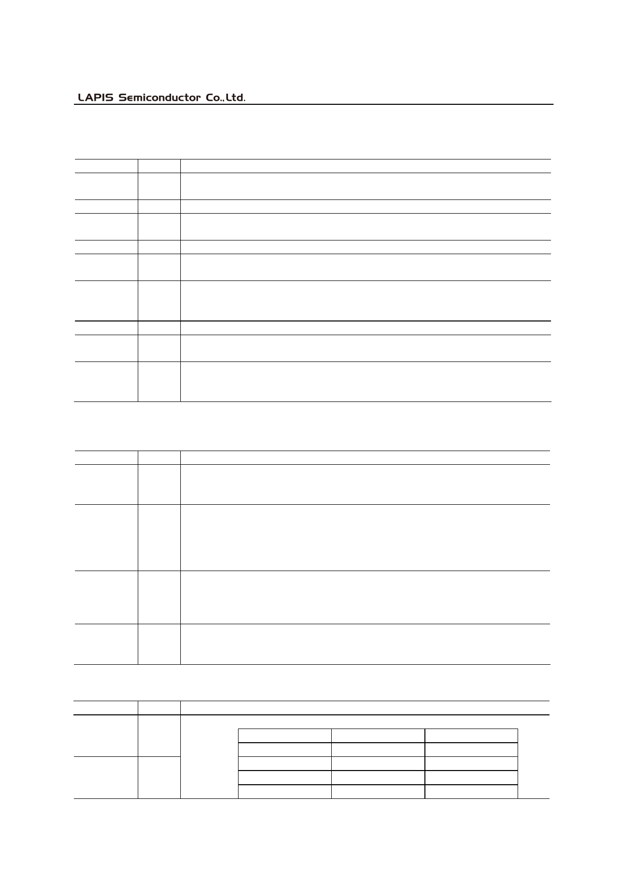
Other Interface
Symbol
SPEED 1
SPEED 0
I/O
Description
Data Transmission Speed between DTE and DCE
I
SPEED 1
SPEED 0
0
0
0
1
I
1
0
1
1
Speed
300 bps
1200 bps
2400 bps
9600 bps
5/23
Share Link: 