CS5180-CL Ver la hoja de datos (PDF) - Cirrus Logic
Número de pieza
componentes Descripción
Lista de partido
CS5180-CL Datasheet PDF : 28 Pages
| |||
CS5180
GENERAL DESCRIPTION
The CS5180 is a monolithic CMOS 16-bit A/D
converter designed to operate in a continuous mode
after being reset.
The CS5180 can operate in a modulator-only mode
in which the unfiltered bit stream from the modula-
tor is the data output from the device.
THEORY OF OPERATION
The front page of this data sheet illustrates the
block diagram of the CS5180.
Converter Initialization: Calibration and
Synchronization
The CS5180 does not have an internal power-on re-
set circuit. Therefore when power is first applied to
the device the RESET pin should be held low until
power is established and the voltage reference has
stabilized. This resets the converter’s logic to a
known state. When power is fully established the
converter will perform a self-calibration, starting
with the first MCLK rising edge after RESET goes
high. The converter will use 988,205 MCLK cycles
to complete the calibration and to allow the digital
filter to fully settle, after which, it will output fully-
settled conversion words. The converter will then
continue to output conversion words at an output
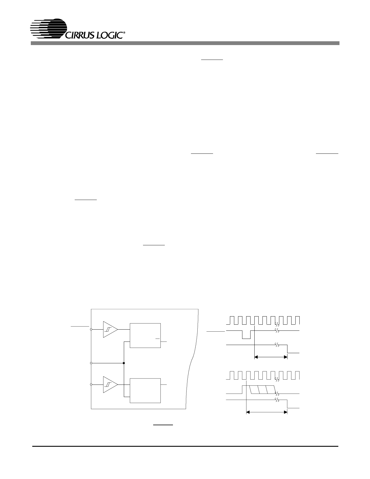
word rate equal to MCLK/64. Figure 2 illustrates
the RESET and SYNC logic and timing for the con-
verter.
The CS5180 is designed to perform conversions
continuously with an output rate that is equivalent
to MCLK/64. The conversions are performed and
the serial port is updated independent of external
controls. The converter is designed to measure dif-
ferential bipolar input signals, and unipolar signals,
with a common mode voltage of between 1.0 V and
VREF + 0.25 V. Calibration is performed when the
RESET signal to the device is released. If RESET
is properly framed to MCLK, the converter can be
synchronized to a specific MCLK cycle at the sys-
tem level.
The SYNC signal can also be used to synchronize
multiple converters in a system. When SYNC is
used, the converter does not perform calibration.
The SYNC signal is recognized on the first rising
edge of MCLK after SYNC goes high. SYNC
aligns the output conversion to occur every 64
MCLK clock cycles after the SYNC signal is rec-
ognized and the filter is settled. After the SYNC is
initiated by going high, the converter will wait
5,161 MCLK cycles for the digital filter to settle
before putting out a fully-settled conversion word.
To synchronize multiple converters in a system, the
RESET
MCLK
SYNC
CS5180
D
Q
CLK
Q RESET
MCLK
RESET
FSO
D
Q SYNC
CLK
MCLK
988205 MCLK Cycles
SYNC
FSO
5161 MCLK Cycles
Figure 2. RESET and SYNC logic and timing.
9
Share Link: 