A8251 Ver la hoja de datos (PDF) - Altera Corporation
Número de pieza
componentes Descripción
Lista de partido
A8251 Datasheet PDF : 21 Pages
| |||
a8251 Programmable Communications Interface Data Sheet
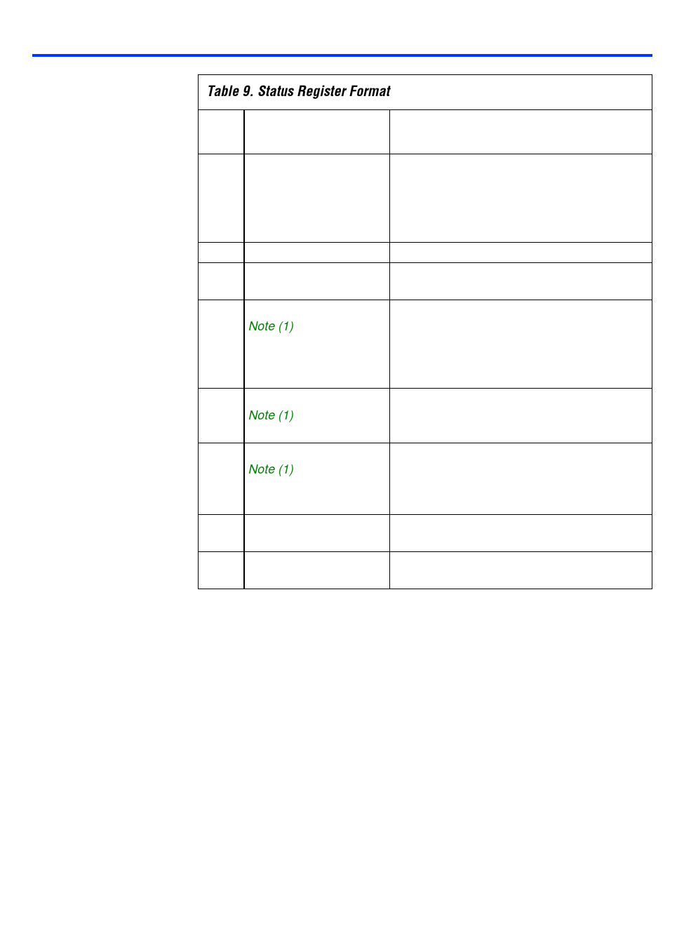
Table 9. Status Register Format
Data
Signal Name
Bit
Function
0 Transmitter ready
(txrdy)
Indicates that the transmitter is ready to
receive another data byte. Unlike the
corresponding output, this bit is not conditional
upon the cts input and the txen command
bit.
1 Receiver ready (rxrdy) Bit 1 reflects the state of the rxrdy signal.
2 Transmitter empty
(txempty)
Bit 2 reflects the state of the txempty signal.
3 Parity error (pe)
Note (1)
When high, bit 3 indicates that the parity bit
received over the rxd input does not match
the parity calculated by the receiver. If no
parity has been selected, this error will not
occur.
4 Overrun error (oe)
Note (1)
Bit 4 indicates that data was ready to write into
the RBR before the previous contents of the
register were read by the microprocessor.
5 Framing error (fe)
Note (1)
Bit 5 is set when a received character does not
end with the expected number of stop bits,
which is usually caused by a transmission
error.
6 Sync or break detect Bit 6 reflects the state of the syn_brk output.
(syn_brk)
7 Data set ready (dsr)
Bit 7 reflects the logical inverse of the state of
the ndsr input.
Note:
(1) A pe, oe, or fe error signal can be cleared by a total state reset (see “Reset
Operation” section on page 42), by an internal state reset, or by writing a logic high
to bit 4 (er) of the command instruction register.
Sync Character One Register
The sync character one register holds the first sync character. The
information is used by the receiver for sync comparison and by the
transmitter for sync character transmission.
Altera Corporation
33
Share Link: 