CB35000 Ver la hoja de datos (PDF) - STMicroelectronics
Número de pieza
componentes Descripción
Lista de partido
CB35000 Datasheet PDF : 16 Pages
| |||
CB35000 SERIES
DESIGN ENVIRONMENT
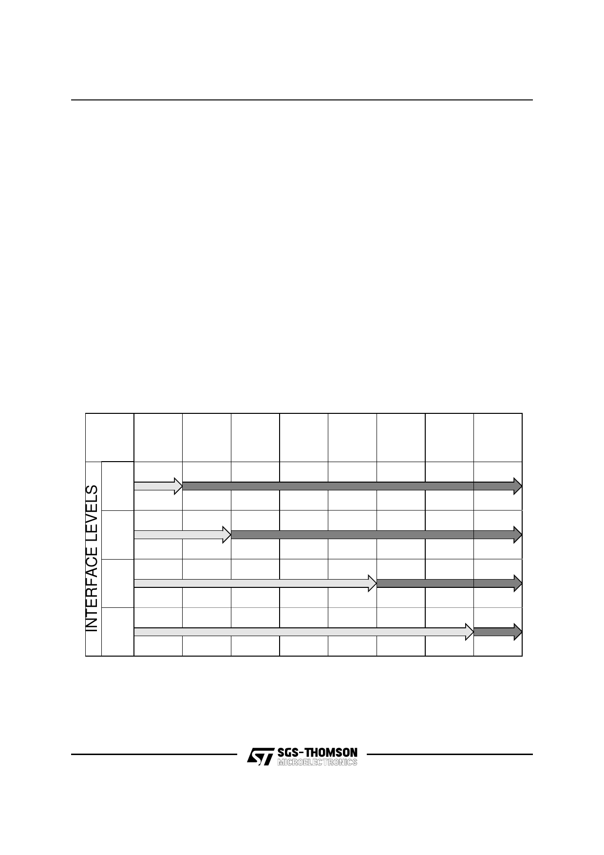
Several interface levels are possible between
SGS-THOMSON and the customer in the
undertaking of an ASIC design. The four levels of
interface are shown in Figure 7. Level 1 is
characterized by SGS-THOMSON receiving the
system specification and taking the design
through to validation and fabrication. At level 2
interface the designer supplies a complete logic
design implemented in a standard generic logic
family. SGS-THOMSON then takes the design
through to layout, validation and fabrication.
Level 3 is the most common and preferred
interface level. Logic capture and pre-layout
simulation are performed by the designer using
an SGS-THOMSON supported design kit. The
design is then taken through layout, validation
and fabrication by SGS-THOMSON.
The SGS-THOMSON design system validates all
designs before fabrication. Design kits are
provided that allow schematic capture entry via
Mentor Graphics and Cadence products.
Simulation is supported for Cadence and Mentor
Graphics. Full support is also provided for
Cadence Verilog, Synopsys VSS and System
Hilo simulators. Figure 8 shows the SGS-
THOMSON Design Flow.
Test vector development uses TSSI software
from Summit and Currentest from CrossCheck.
Figure 7
Customer/SGS-THOMSON Interface Levels
SYSTEM
SYSTEM
SPECIFICATION
LOGIC
DESIGN
SCHEMATIC
DESIGN
PRE-LAYOUT
CAPTURE VERIFICATION SIMULATION
LAYOUT
POST-LAYOUT MANUFACTURE
SIMULATION AND TEST
CUSTOMER
LEVEL 1
SGS-THOMSON
LEVEL 2
CUSTOMER
SGS-THOMSON
LEVEL 3
CUSTOMER
SGS-THOMSON
LEVEL 4
CUSTOMER
ECR1
SGS-THOMSON
ECR2
10/16
®
Share Link: 