MD82C288-10 Ver la hoja de datos (PDF) - Intel
Número de pieza
componentes Descripción
Lista de partido
MD82C288-10 Datasheet PDF : 20 Pages
| |||
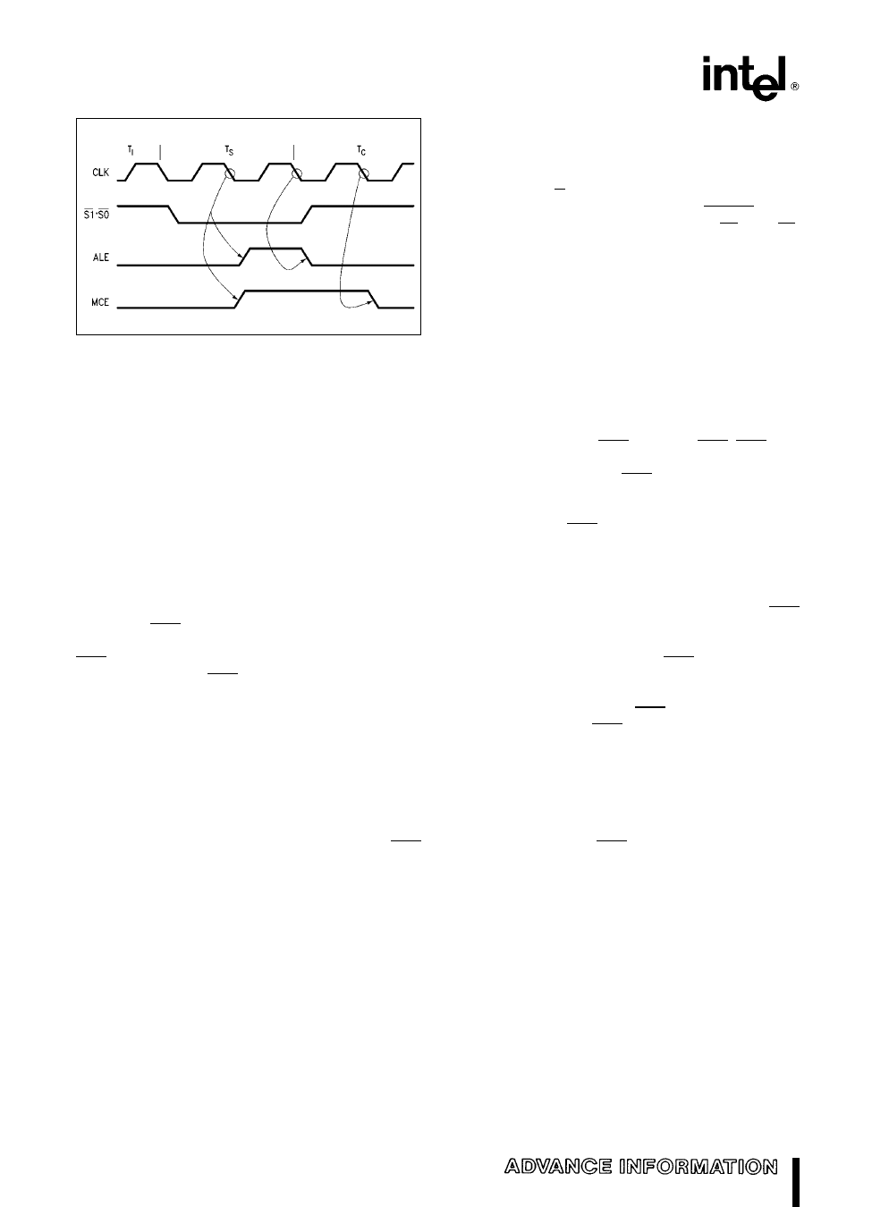
M82C288
271077 – 11
Figure 11 MCE Operation for an INTA Bus Cycle
Control Inputs
The control inputs can alter the basic timing of com-
mand outputs allow interfacing to multiple buses
and share a bus between different masters For
many M80286 systems each CPU will have more
than one bus which may be used to perform a bus
cycle Normally a CPU will only have one bus con-
troller active for each bus cycle Some buses may be
shared by more than one CPU (i e MULTIBUS) re-
quiring only one of them use the bus at a time
Systems with multiple and shared buses use two
control input signals of the M82C288 bus controller
CENL and AEN (see Figure 12) CENL enables the
bus controller to control the current bus cycle The
AEN input prevents a bus controller from driving its
command outputs AEN HIGH means that another
bus controller may be driving the shared bus
In Figure 12 two buses are shown a local bus and a
MULTIBUS I Only one bus is used for each CPU
bus cycle The CENL inputs of the bus controller
select which bus controller is to perform the bus cy-
cle An address decoder determines which bus to
use for each bus cycle The M82C288 connected to
the shared MULTIBUS I must be selected by CENL
and be given access to the MULTIBUS I by AEN
before it will begin a MULTIBUS I operation
CENL must be sampled HIGH at the end of the TS
bus state (see waveforms) to enable the bus control-
ler to activate its command and control outputs If
sampled LOW the commands and DEN will not go
active and DT R will remain HIGH The bus control-
ler will ignore the CMDLY CEN and READY inputs
until another bus cycle is started via S1 and S0
Since an address decoder is commonly used to
identify which bus is required for each bus cycle
CENL is latched to avoid the need for latching its
inputs
The CENL input can affect the DEN control output
When MB e 0 DEN normally becomes active dur-
ing Phase 2 of TS in write bus cycles This transition
occurs before CENL is sampled If CENL is sampled
LOW the DEN output will be forced LOW during TC
as shown in the timing waveforms
When MB e 1 CEN AEN becomes AEN AEN con-
trols when the bus controller command outputs en-
ter and exit 3-state OFF AEN is intended to be driv-
en by a MULTIBUS I type bus arbiter which assures
only one bus controller is driving the shared bus at
any time When AEN makes a LOW to HIGH tran-
sition the command outputs immediately enter
3-state OFF and DEN is forced inactive An inactive
DEN should force the local data transceivers con-
nected to the shared data bus into 3-state OFF (see
Figure 12) The LOW to HIGH transition of AEN
should only occur during TI or TS bus states
The HIGH to LOW transition of AEN signals that the
bus controller may now drive the shared bus com-
mand signals Since a bus cycle may be active or be
in the process of starting AEN can become active
during any T-state AEN LOW immediately allows
DEN to go the appropriate state Three CLK edges
later the command outputs will go active (see timing
waveforms) The MULTIBUS I requires this delay for
the address and data to be valid on the bus before
the command becomes active
When MB e 0 CEN AEN becomes CEN CEN is an
asynchronous input which immediately affects the
command and DEN outputs When CEN makes a
HIGH to LOW transition the commands and DEN
10
Share Link: 