MD82C288-10 Ver la hoja de datos (PDF) - Intel
Número de pieza
componentes Descripción
Lista de partido
MD82C288-10 Datasheet PDF : 20 Pages
| |||
M82C288
Symbol
CEN AEN
ALE
MCE
DEN
DT R
IOWC
IORC
MWTC
MRDC
Type
I
O
O
O
O
O
O
O
O
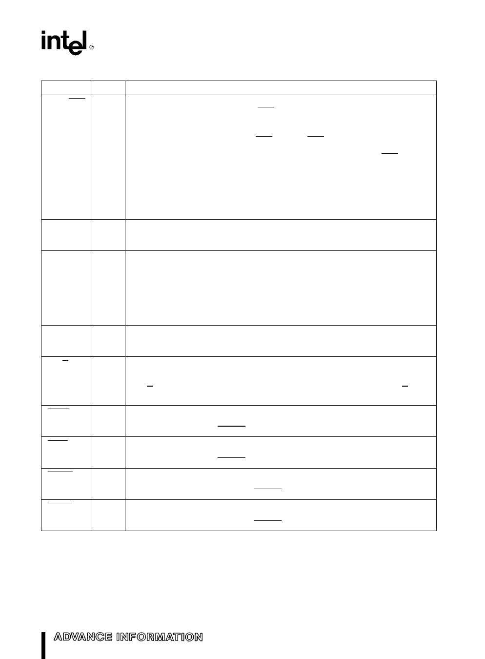
Table 1 Pin Description (Continued)
Name and Function
COMMAND ENABLE ADDRESS ENABLE controls the command and DEN
outputs of the bus controller CEN AEN inputs may be asynchronous to CLK
Setup and hold times are given to assure a guaranteed response to synchronous
inputs This input may be connected to VCC or GND
When MB is HIGH this pin has the AEN function AEN is an active LOW input which
indicates that the CPU has been granted use of a shared bus and the bus controller
command outputs may exit 3-state OFF and become inactive (HIGH) AEN HIGH
indicates that the CPU does not have control of the shared bus and forces the
command outputs into 3-state OFF and DEN inactive (LOW)
When MB is LOW this pin has the CEN function CEN is an unlatched active HIGH
input which allows the bus controller to activate its command and DEN outputs
With MB LOW CEN LOW forces the command and DEN outputs inactive but does
not tristate them
ADDRESS LATCH ENABLE controls the address latches used to hold an address
stable during a bus cycle This control output is active HIGH ALE will not be issued
for the halt bus cycle and is not affected by any of the control inputs
MASTER CASCADE ENABLE signals that a cascade address from a master
M8259A interrupt controller may be placed onto the CPU address bus for latching
by the address latches under ALE control The CPU’s address bus may then be
used to broadcast the cascade address to slave interrupt controllers so only one of
them will respond to the interrupt acknowledge cycle This control output is active
HIGH MCE is only active during interrupt acknowledge cycles and is not affected
by any control input Using MCE to enable cascade address drivers requires
latches which save the cascade address on the falling edge of ALE
DATA ENABLE controls when data transceivers connected to the local data bus
should be enabled DEN is an active HIGH control output DEN is delayed for write
cycles in the MULTIBUS I mode
DATA TRANSMIT RECEIVE establishes the direction of data flow to or from the
local data bus When HIGH this control output indicates that a write bus cycle is
being performed A LOW indicates a read bus cycle DEN is always inactive when
DT R changes states This output is HIGH when no bus cycle is active DT R is not
affected by any of the control inputs
I O WRITE COMMAND instructs an I O device to read the data on the data bus
This command output is active LOW The MB and CMDLY input control when this
output becomes active READY controls when it becomes inactive
I O READ COMMAND instructs an I O device to place data onto the data bus
This command output is active LOW The MB and CMDLY input control when this
output becomes active READY controls when it become inactive
MEMORY WRITE COMMAND instructs a memory device to read the data on the
data bus This command output is active LOW The MB and CMDLY inputs control
when this output becomes active READY controls when it becomes inactive
MEMORY READ COMMAND instructs the memory device to place data onto the
data bus This command output is active LOW The MB and CMDLY inputs control
when this output becomes active READY controls when it becomes inactive
3
Share Link: 