ADM1023 Ver la hoja de datos (PDF) - Analog Devices
Número de pieza
componentes Descripción
Lista de partido
ADM1023 Datasheet PDF : 12 Pages
| |||
ADM1023
4
100
80
3
60
10mV p-p
2
40
20
1
0
0
100k
1M
10M
100M
1G
FREQUENCY – Hz
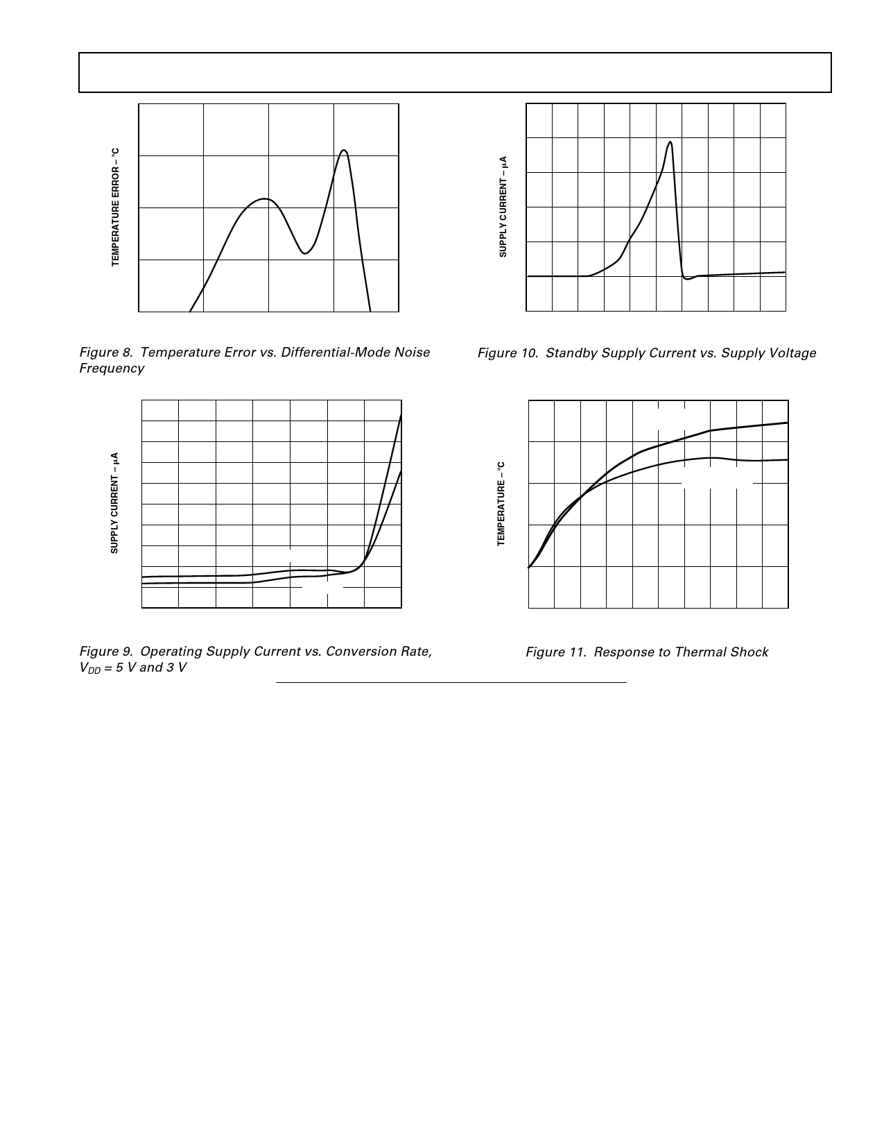
Figure 8. Temperature Error vs. Differential-Mode Noise
Frequency
–20
0
0.5 1.0 1.5 2.0 2.5 3.0 3.5 4.0 4.5 5.0
SUPPLY VOLTAGE – V
Figure 10. Standby Supply Current vs. Supply Voltage
550
500
450
400
350
300
250
200
3.3 VOLTS
150
100
5 VOLTS
50
0.0625 0.125 0.25 0.5
1
2
4
8
CONVERSION RATE – Hz
Figure 9. Operating Supply Current vs. Conversion Rate,
VDD = 5 V and 3 V
125
REMOTE
TEMPERATURE
100
INT
75
TEMPERATURE
50
25
0
0
12
3
4
5
6
78
9 10
TIME – Seconds
Figure 11. Response to Thermal Shock
FUNCTIONAL DESCRIPTION
The ADM1023 contains a two-channel, A-to-D converter with
special input-signal conditioning to enable operation with remote
and on-chip diode temperature sensors. When the ADM1023
is operating normally, the A-to-D converter operates in a
free-running mode. The analog input multiplexer alternately
selects either the on-chip temperature sensor to measure its
local temperature, or the remote temperature sensor. These
signals are digitized by the ADC and the results are stored in
the Local and Remote Temperature Value Registers. Only
the eight most significant bits of the local temperature value
are stored as an 8-bit binary word. The remote temperature value
is stored as an 11-bit, binary word in two registers. The eight
MSBs are stored in the Remote Temperature Value High Byte
Register at address 01h. The three LSBs are stored, left-justified,
in the Remote Temperature Value High Byte Register at
address 10h.
Error sources such as PCB track resistance and clock noise
can introduce offset errors into measurements on the Remote
Channel. To achieve the specified accuracy on this channel,
these offsets must be removed, and two Offset Registers are
provided for this purpose at addresses 11h and 12h.
An offset value may automatically be added to or subtracted
from the measurement by writing an 11 bit, two’s complement
value to registers 11h (high byte) and 12h (low byte, left-
justified).
The offset registers default to zero at power-up and will have no
effect if nothing is written to them.
The measurement results are compared with Local and Remote,
High and Low Temperature Limits, stored in six on-chip Limit
Registers. As with the measured value, the local temperature
limits are stored as 8-bit values and the remote temperature limits
as 11-bit values. Out-of-limit comparisons generate flags that
are stored in the status register, and one or more out-of-limit
results will cause the ALERT output to pull low.
Registers can be programmed, and the device controlled and
configured, via the serial System Management Bus. The con-
tents of any register can also be read back via the SMBus.
Control and configuration functions consist of:
• Switching the device between normal operation and standby
mode.
• Masking or enabling the ALERT output.
• Selecting the conversion rate.
On initial power-up the remote and local temperature values
default to –128°C. Since the device normally powers up convert-
ing, a measure of local and remote temperature is made and these
REV. A
–5–
Share Link: 