AD2S100 Ver la hoja de datos (PDF) - Analog Devices
Número de pieza
componentes Descripción
Lista de partido
AD2S100 Datasheet PDF : 12 Pages
| |||
AD2S100
THEORY OF OPERATION
A fundamental requirement for high quality induction motor
drives is that the magnitude and position of the rotating air-gap
rotor flux be known. This is normally carried out by measuring
the rotor position via a position sensor and establishing a rotor
reference frame that can be related to stator current coordinates.
To generate a flux component in the rotor, stator current is ap-
plied. A build-up of rotor flux is concluded which must be
maintained by controlling the stator current, ids, parallel to the
rotor flux. The rotor flux current component is the magnetizing
current, imr.
Torque is generated by applying a current component which is
perpendicular to the magnetizing current. This current is nor-
mally called the torque generating current, iqs.
To orient and control both the torque and flux stator current
vectors, a coordinate transformation is carried out to establish a
new reference frame related to the rotor. This complex calcula-
tion is carried out by the AD2S100 vector processor.
To expand upon the vector operator a description of a single
vector rotation is of assistance. If it is considered that the mod-
uli of a vector is OP and that through the movement of rotor
position by , we require the new position of this vector it can
be deduced as follows:
Let original vector OP = A (Cos + jSIN ) where A is a
constant;
so if OQ = OP ej
(1)
and: ej = Cos + jSin
OQ = A (Cos ( + ) + jSin ( + ))
= A [Cos Cos φ – Sin Sin φ + jSin Cos φ + jCos Sin φ]
= A [(Cos + jSin ) (Cos + jSin )]
(2)
a
Q
θ+φ
P
φ
θ
d
O
To relate these stator current to the reference frame the rotor
currents assume the same rectangular coordinates, but are now
rotated by the operator ej, where ej = Cos + jSin .
Here the term vector rotator comes into play where the stator
current vector can be represented in rotor-based coordinates or
vice versa.
The AD2S100 uses ej as the core operator. Here represents
the digital position angle which rotates as the rotor moves. In
terms of the mathematical function, it rotates the orthogonal ids
and iqs components as follows:
ids' + jiqs' = (Ids + jIqs) ej
where ids', iqs' = stator currents in the rotor reference frame. And
ej = Cos + jSin
= (Ids + jIqs)(Cos + jSin )
The output from the AD2S100 takes the form of:
ids' = Ids Cos – Iqs Sin
iqs' = Ids Sin + Iqs Cos
The matrix equation is:
[ ] [ ] [ ] ids' = Cos – Sin
Ids
iqs'
Sin Cos
Iqs
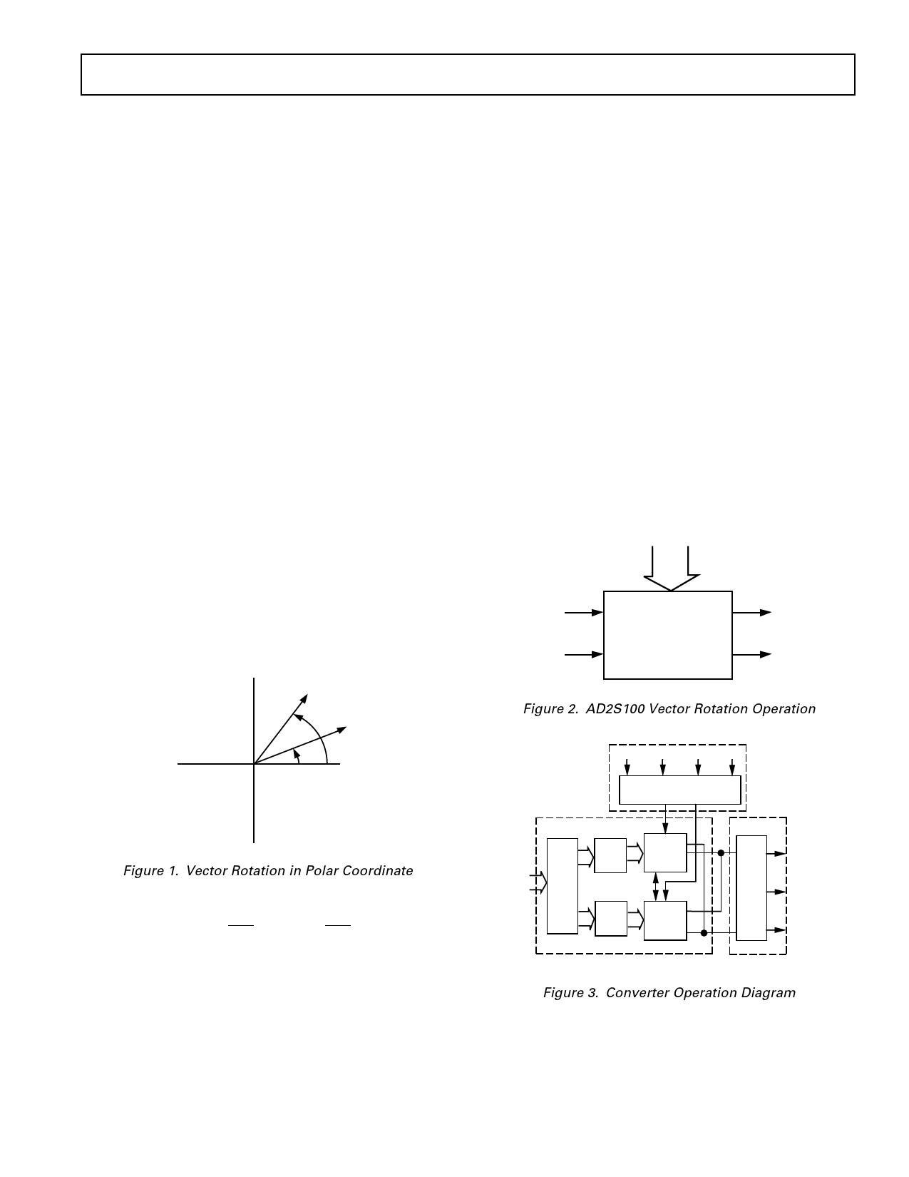
and it is shown in Figure 2.
φ
ids
ids'
ejφ
iqs
iqs'
Figure 2. AD2S100 Vector Rotation Operation
INPUT CLARK
COSθ COSθ + 120° COSθ + 240° SINθ
3φ + 2φ
TRANSFORMATION
Figure 1. Vector Rotation in Polar Coordinate
The complex stator current vector can be represented as is = ias
+ aibs + a2ics where a = e
j 2π and a2 = e
3
j 4π . This can be re-
3
placed by rectangular coordinates as
is = ids + jiqs
(3)
In this equation ids and iqs represent the equivalent of a two-
phase stator winding which establishes the same magnitude of
MMF in a three-phase system. These inputs can be seen after
the three-phase to two-phase transformation in the AD2S100
block diagram. Equation (3) therefore represents a three-phase
to two-phase conversion.
DIGITAL
φ
LATCH
LATCH
LATCH
SINE AND
COSINE
MULTIPLIER
(DAC)
SINE AND
COSINE
MULTIPLIER
(DAC)
Cos(θ + φ)
2φ–3φ
Cos(θ +(120° + φ))
Cos(θ +(240° + φ))
PARK
OUTPUT CLARK
Figure 3. Converter Operation Diagram
REV. A
–5–
Share Link: 