AD2S100 Ver la hoja de datos (PDF) - Analog Devices
Número de pieza
componentes Descripción
Lista de partido
AD2S100 Datasheet PDF : 12 Pages
| |||
AD2S100
Output Analog Signals
There are three forms of analog output from the AD2S100.
Sin/Cos orthogonal output signals are derived from the Clark/
three-to-two-phase conversion before the Park angle rotation.
These signals are available on Pin 25 (Cos ) and Pin 26 (Sin
), and occur before Park angle rotation.
Three-Phase Output Signals
(Cos (θ + φ), Cos (φ + θ + 120°), Cos (φ + θ + 240°)), where
φ represents digital input angle. These signals are available on
Pin 7 (PH/OP1), Pin 9 (PH/OP2) and Pin 8 (PH/OP3),
respectively.
Two-Phase (Sin (θ + φ), Cos (θ + φ)) Signals
These represent the output of the coordinate transformation.
These signals are available on Pin 6 (PH/OP4, Sin (θ + φ)) and
Pin 7 (PH/OP1, Cos (θ + φ)).
HOMOPOLAR OUTPUT
HOMOPOLAR Reference
In a three-phase ac system, the sum of the three inputs to the
converter can be used to indicate whether or not the phases are
balanced.
If VSUM = PH/IP1 + PH/IP2 + PH/IP3 (or PH/IPH1 +
PH/IPH2 + PH/IPH3) this can be rewritten as VSUM = [Cos, +
Cos ( + 120°) + Cos ( + 240°)] = 0. Any imbalances in the
line will cause the sum VSUM ≠ 0. The AD2S100 homopolar
output (HPOP) goes high when VSUM > 3 × Vts. The voltage
level at which the HPOP indicates an imbalance is determined
by the HPREF threshold, Vts. This is set internally at ± 0.5 V dc
(± 0.1 V dc). The HPOP goes high when
V ts
<
(Cosθ
+
Cos( θ
+ 120° ) +
3
Cos( θ
+
240°
))
×V
where V is the nominal input voltage.
With no external components VSUM must exceed ± 1.5 V dc in
order for HPOP to indicate an imbalance. The sensitivity of the
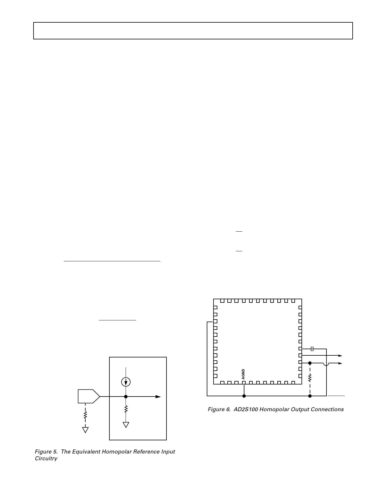
threshold can be reduced by connecting an external resistor be-
tween HPOP and ground in Figure 5 where,
REXT = Ω
Vts = V dc.
V ts
=
0.5 REXT
REXT + 20000
HOMOPOLAR
REFERENCE
25µA
TO TRIGGER
Example: From the equivalent circuit, it can be seen that the in-
clusion of a 20 kΩ resistor will reduce Vts to ± 0.25 V dc. This
corresponds to an imbalance of ± 0.75 V dc in the inputs.
Homopolar Filtering
The equation VSUM = Cos + Cos ( + 120°) + Cos ( + 240°)
= 0 denotes an imbalance when VSUM ≠ 0. There are conditions,
however, when an actual imbalance will occur and the condi-
tions as defined by VSUM will be valid. For example, if the first
phase was open circuit when = 90° or 270°, the first phase is
valid at 0 V dc. VSUM is valid, therefore, when Cos is close to 0.
In order to detect an imbalance has to move away from 90° or
270°, i.e., when on a balanced line Cos ≠ 0.
Line imbalance is detected as a function of HPREF, either set
by the user or internally set at ± 0.5 V dc. This corresponds to a
dead zone when = 90° or 270° ± 30°, i.e., VSUM = 0, and,
therefore, no indicated imbalance. If an external 20 kΩ resistor
is added, this halves Vts and reduces the zone to ± 15°. Note this
example only applies if the first phase is detached.
In order to prevent this false triggering an external capacitor
needs to be placed from HPFILT to ground, as shown in Figure
5. This averages out the perceived imbalance over a complete
cycle and will prevent the HPOP from alternatively indicating
balance and imbalance over = 0° to 360°.
For
dθ = 1000 rpm CEXT = 200 nF
dt
dθ = 100 rpm CEXT = 2.2 µF
dt
Note: The slower the input rotational speed, the larger the time
constant required over which to average the HPOP output. Use
of the homopolar output at slow rotational speeds becomes
impractical with respect to the increased value for CEXT.
34
DGND
1
AD2S100
TOP VIEW
12
23
HPFILT
HPOP
HPREF
CEXT
220nF
HPOP
HPREF
REXT
GND
EXTERNAL
RESISTOR
20kΩ
Figure 6. AD2S100 Homopolar Output Connections
Figure 5. The Equivalent Homopolar Reference Input
Circuitry
REV. A
–7–
Share Link: 