AD2S100 Ver la hoja de datos (PDF) - Analog Devices
Número de pieza
componentes Descripción
Lista de partido
AD2S100 Datasheet PDF : 12 Pages
| |||
AD2S100
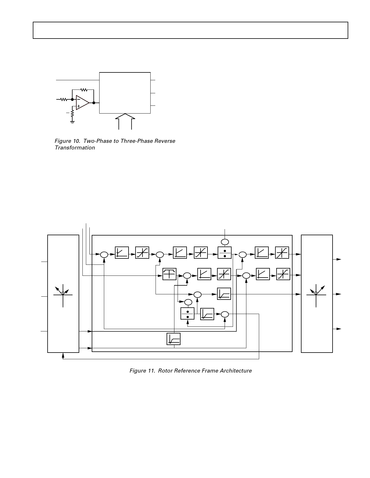
√In Figure 9, “–1” operator performs a 180° phase shift opera-
tion. It can be illustrated by a 2-phase-to-3-phase reverse trans-
formation. An example is shown in Figure 10.
Cosθ
R
R
Sinθ
R
2
PH/IP1 (Cosθ)
PH/OP1
Cos(θ + φ)
AD2S100
PH/OP3
Cos(θ + 240° + φ)
PH/IP4 (Sinθ)
PH/OP2
Cos(θ + 120° + φ)
Cos(θ – φ)
Cos(θ + 120° – φ)
Cos(θ + 240° – φ)
φ
Figure 10. Two-Phase to Three-Phase Reverse
Transformation
Field Oriented Control of AC Induction Machine in a Rotor
Flux Frame
The architecture shown in Figure 11 identifies a simplified
scheme where the AD2S100 permits the DSP computing core
to execute the motor control in what is normally termed the
rotor reference frame. This reference frame actually operates in
synchronism with the rotor of a motor. This has significant
benefits regarding motor control efficiency and economics. The
calculating power required in the rotor reference frame is signifi-
cantly reduced because the currents and flux are rotating at the
slip frequency. This permits calculations to be carried out in
time frames of, 100 µs, or under by a fixed-point DSP. Bench-
mark timing in this type of architecture can attain floating-point
speed processing with a fixed-point processor. Perhaps the larg-
est advantage is in the ease with which the rotor flux position
can be obtained. A large amount of computation time is, there-
fore, removed by the AD2S100 vector processors due to the
split architecture shown in Figure 11. Motor control systems
employing one DSP to carry out the cartesian to polar transfor-
mations required for vector control are, therefore, tasked with
additional duties due to the fact that they normally operate in
the flux reference frame.
The robustness of the control system can also be increased by
carrying out the control in the rotor reference frame. This is
achieved through the ability to increase and improve both the
algorithm quality in nonlinear calculations attributed to magne-
tizing inductance and rotor time constant for example. An
increase in sampling time can also be concluded with this archi-
tecture by avoiding the additional computing associated with
number truncation and rounding errors which reduce the signal-
to-noise rejection ratio.
POSITION
FEEDBACK
VELOCITY
FEEDBACK
v
v
v
POSITION
SET POINT
CONTROL SOFTWARE ADSP2101
v imrmax
is1
VECTOR
CO-PROCESSOR
(a + jb)e–jρ
SPEED
CONTROL
+ ε'
–
ε
LIMIT
+ ω'
TORQUE
CONTROL
LIMIT
md'
–
ω
FIELD
WEAKENING
+ imr'
–
imr
Cm
+ iqs'
–
iqs
+ ids'
–
ids
is2
REVERSE
ROTATION
is3
iqs
ω+
+ ω2
Tr
iqs
ω1
θ2
+
+ε
Vqs'
VECTOR
Vs1
CO-PROCESSOR
Vds' (a + jb)e'–jρ'
ρ'
Vs2
FORWARD
ROTATION
Vs3
AD2S100
ids
ρ
AD2S100
Figure 11. Rotor Reference Frame Architecture
REV. A
–9–
Share Link: 