IRHQ6110 Ver la hoja de datos (PDF) - International Rectifier
Número de pieza
componentes Descripción
Lista de partido
IRHQ6110 Datasheet PDF : 14 Pages
| |||
IRHQ6110
Pre-Irradiation
International Rectifier Radiation Hardened MOSFETs are tested to verify their radiation hardness capability.
The hardness assurance program at International Rectifier is comprised of two radiation environments.
Every manufacturing lot is tested for total ionizing dose (per notes 5 and 6) using the TO-3 package. Both
pre- and post-irradiation performance are tested and specified using the same drive circuitry and test
conditions in order to provide a direct comparison.
Table 1. Electrical Characteristics For Each N-Channel Device @ Tj = 25°C, Post Total Dose Irradiation ÄÅ
Parameter
100KRads(Si)1 300K to 1000K Rads (Si)2 Units
Min Max Min Max
Test Conditions
BVDSS
VGS(th)
IGSS
IGSS
IDSS
RDS(on)
RDS(on)
VSD
Drain-to-Source Breakdown Voltage
Gate Threshold Voltage
Gate-to-Source Leakage Forward
Gate-to-Source Leakage Reverse
Zero Gate Voltage Drain Current
Static Drain-to-Source Ã
On-State Resistance (TO-3)
Static Drain-to-Source Ã
On-State Resistance (LCC-28)
Diode Forward Voltage Ã
100 —
2.0 4.0
— 100
— -100
—
25
— 0.556
— 0.60
—
1.2
100
1.25
—
—
—
—
—
—
—
V
4.5
100 nA
-100
25 µA
0.706 Ω
0.75 Ω
1.2 V
VGS = 0V, ID = 1.0mA
VGS = VDS, ID = 1.0mA
VGS = 20V
VGS = -20 V
VDS= 80V, VGS =0V
VGS = 12V, ID = 1.9A
VGS = 12V, ID = 1.9A
VGS = 0V, IS = 3.0A
1. Part number IRHQ6110
2. Part number IRHQ63110
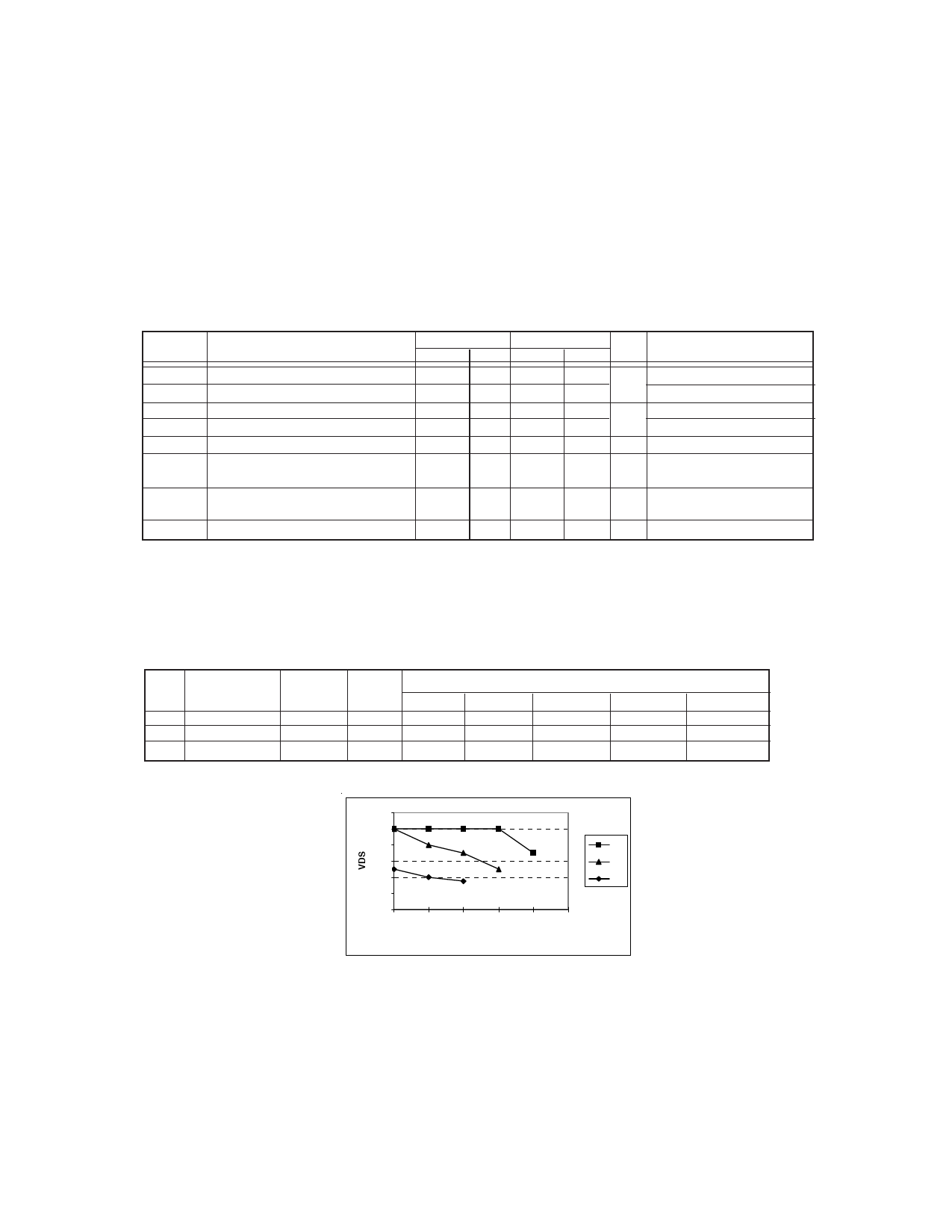
International Rectifier radiation hardened MOSFETs have been characterized in heavy ion environment for
Single Event Effects (SEE). Single Event Effects characterization is illustrated in Fig. a and Table 2.
Table 2. Single Event Effect Safe Operating Area
Ion
LET
MeV/(mg/cm2))
Cu
28.0
Br
36.8
I
59.8
Energy
(MeV)
285
305
343
Range
(µm)
43.0
39.0
32.6
@VGS=0V @VGS=-5V
100
100
100
80
50
40
VDS (V)
@VGS=-10V
100
70
35
@VGS=-15V
100
50
—
@VGS=-20V
70
—
—
120
100
80
Cu
60
Br
40
I
20
0
0
-5
-10
-15 -20 -25
VGS
Fig a. Single Event Effect, Safe Operating Area
For footnotes, refer to the last page
4
www.irf.com
Share Link: 