IC555 Ver la hoja de datos (PDF) - Fairchild Semiconductor
Número de pieza
componentes Descripción
Lista de partido
IC555 Datasheet PDF : 14 Pages
| |||
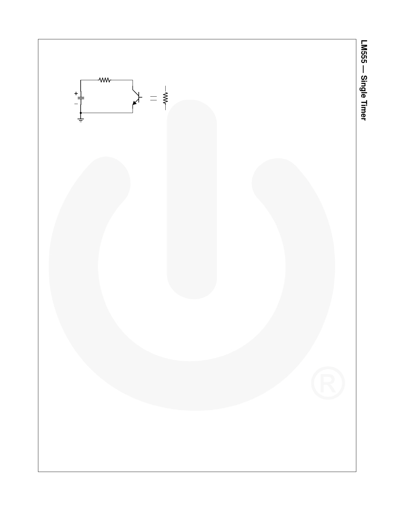
The equivalent circuit for discharging capacitor C1, when timer output is low is, as follows:
RB
C1 VC1(0-)=2Vcc/3
RD
C1 d----v-d---C-t---1--
+
-----------1------------
RA + RB
VC1
=
0
- ------------------t------------------
VC1(t)
=
2--
3
VCCe
(RA
+
RD)C1
(6)
(7)
Since the duration of the timer output low state (tL) is the amount of time it takes for the VC1(t) to reach VCC/3,
13-- VCC
=
23---
V
C
-(---R----A------+---t--RL----D-----)---C----1--
Ce
(8)
tL = C1(RB + RD)In2 = 0.693(RB + RD)C1
(9)
Since RD is normally RB>>RD although related to the size of discharging transistor,
tL = 0.693RBC1
(10)
Consquently, if the timer operates in astable, the period is the same with
't = tH+tL = 0.693(RA+RB)C1+0.693RBC1 = 0.693(RA+2RB)C1'
because the period is the sum of the charge time and discharge time. Since frequency is the reciprocal of the period,
the following applies:
frequency,
f
=
1--
t
=
(---R----A------+--1---2.--4--R-4---B-----)--C-----1-
( 11 )
© 2002 Fairchild Semiconductor Corporation
LM555 Rev. 1.1.0
7
www.fairchildsemi.com
Share Link: 