CS8920A Ver la hoja de datos (PDF) - Cirrus Logic
Número de pieza
componentes Descripción
Lista de partido
CS8920A Datasheet PDF : 144 Pages
| |||
CS8920A
• A reset signal on the system bus places all
Plug and Play cards into a mode in which
they are all waiting for configuration to be-
gin.
• A special key is written to all all of the PNP
cards to initialize them for selection.
• A special series of reads is performed that
allows a single card to be selected. The se-
lected card is given a system identifier, called
the card select number (CSN). The configu-
ration software then determines the resource
requirements of the card. Finally, the selected
card is placed into a sleep mode. The remain-
ing cards are individually selected and
assigned a CSN and their resource needs de-
termined.
• The configuration software then selects an
individual card using the CSN, assigns non-
conflicting resources to the card, and then
enables the card for normal operation. This is
repeated for each of the Plug and Play cards
until all of the cards have been configured
and enabled.
Plug and Play Auxiliary Key
The CS8920A will respond to a special auxiliary
key at any time. The auxiliary initiation key is
normally used for testing/debug purposes. Two
bytes of 00 should proceed the initiation or aux-
iliary key. This auxiliary initiation key is listed
below in hexadecimal:
6A, B5, DA, 6D, B6, 5B, 2D, 16
0B, 05, 02, 01, 80, C0, 60, 30
18, 0C, 06, 83, 41, 20, 90, 48
24, 12, 89, C4, E2, F1, F8, FC
Plug and Play Device IDs
The Plug and Play device ID is a unique identi-
fier that is used by the operating system to
associate the Plug and Play card with its device
DS238PP2
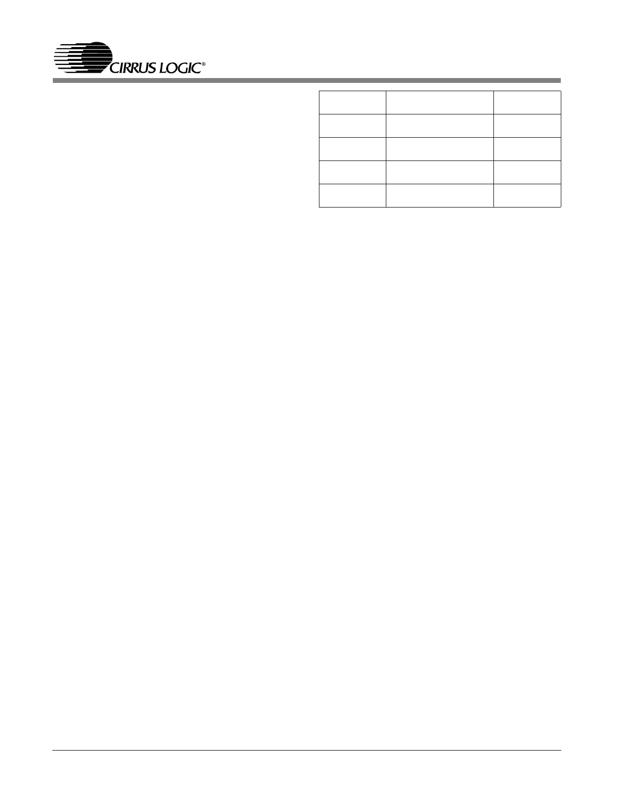
CS8920A Pin
(Pin #)
EECS
(Pin 141)
EESK
(Pin 142)
EEDO
(Pin 6)
EEDI
(Pin 7)
CS8920A Function
EEPROM Chip
Select
1 MHz EEPROM Serial
Clock output
EEPROM Data Out
(data to EEPROM)
EEPROM Data In (data
from EEPROM)
EEPROM
Pin
Chip Select
Clock
Data In
Data Out
Table 3.5. EEPROM Interface
driver. Microsoft administers the assignment of
these device IDs. Contact Microsoft to receive a
unique device ID.
3.5 Configuration with EEPROM
EEPROM Interface
The interface to the EEPROM consists of the
four signals shown in Table 3.5
EEPROM Memory Organization
EEPROM is used to store initial configuration
information for the CS8920A. The EEPROM is
organized in one or more blocks of 16-bit words.
The first block in EEPROM, referred to as the
Configuration Block, is used to configure the
CS8920A after reset. An example of a typical
Configuration Block is shown in Table 3.6 . Ad-
ditional user data may also be stored in the
EEPROM if space is available. The additional
data are stored as 16-bit words and can occupy
any EEPROM address space beginning immedi-
ately after the end of the Reset Configuration
Block up to address 7Fh, depending on
EEPROM size. This additional data can only be
accessed through software control (refer to Sec-
tion 3.6 for more information on accessing the
EEPROM). Address space 80h to AFh is re-
served
19
Share Link: 