CS8920A Ver la hoja de datos (PDF) - Cirrus Logic
Número de pieza
componentes Descripción
Lista de partido
CS8920A Datasheet PDF : 144 Pages
| |||
CS8920A
Reset Configuration Block
The first block in EEPROM, referred to as the
Reset Configuration Block, is used to automat-
ically program the CS8920A with an initial
configuration after a reset. It is a block of con-
tiguous 16-bit words starting at EEPROM
address 00h. The Reset Configuration Block can
be divided into three logical sections: a header,
one or more groups of configuration data words,
and a checksum value. All of the words in the
Reset Configuration Block are read sequentially
by the CS8920A after each reset, starting with
the header and ending with the checksum. Each
group of configuration data is used to program a
PacketPage register (or set of PacketPage regis-
ters in some cases) with an initial non-default
value.
Reset Configuration Block Header: The header
(first word of the block located at EEPROM ad-
dress 00h) specifies the type of EEPROM used,
whether or not a Reset Configuration block is
present, if the CS8920A’s Plug and Play support
is enabled or disabled, and how many bytes of
data are stored in the Reset Configuration Block.
Determining the EEPROM Type: The LSB of
the high byte of the header indicates the type of
EEPROM attached: sequential or non-sequential.
An LSB of 0 (XXXX-XXX0) indicates a se-
quential EEPROM. An LSB of 1 (XXXX-
XXX1) indicates a non-sequential EEPROM.
The CS8920A works equally well with either
type of EEPROM. The CS8920A will automat-
ically generate sequential addresses while
reading the Reset Configuration Block if a non-
sequential EEPROM is used.
Checking EEPROM for presence of Reset Con-
figuration Block: The readout of either a binary
101X-XXX0 or 101X-XXX1 (X = do not care)
from the high byte of the header indicates the
presence of configuration data. Any other read-
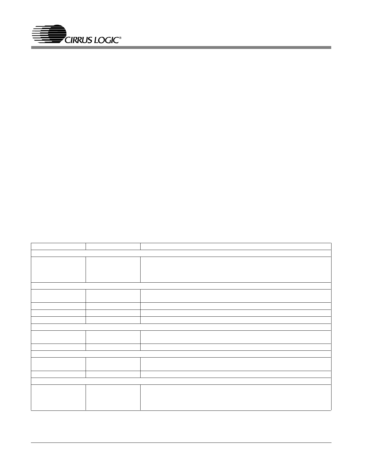
Word Address
Value
FIRST WORD in DATA BLOCK
00h
B112h
FIRST GROUP of WORDS
01h
2158h
02h
0100h
03h
0302h
04h
0504h
SECOND GROUP of WORDS
05h
0360h
06h
0003h
THIRD GROUP of WORDS
07h
0330h
08h
CHECKSUM Value
09h
0001
1B00h
Description
Configuration Block Header.
The high byte, B1h, indicates a ’C56 EEPROM (non-sequential) is attached
and Plug and Play is disabled. The Link Byte, 12h, indicates the number of
bytes of configuration data in this block.
Group Header for first group of words.
Three words to be loaded, beginning at 0158h in PacketPage memory.
Individual address, bits[39-32], bits[47-40]
Individual address, bits[23-16], bits[31-24]
Individual address, bits[7-0], bits[15-8]
Group Header for second group of words.
One word to be loaded at 360h in PacketPage memory.
IO Base address = 300h
Group Header for third group of words.
One word to be loaded at 330h in PacketPage memory.
Set adapter’s activate bit (make active on reset w/o PnP).
The high byte, 1Bh, is the checksum value. The checksum includes word
addresses 00h through 08h. The hexadecimal sum of the bytes is E5h,
resulting in a 2’s complement of 1Bh. The low byte, 00h, provides a pad to
the word boundary.
Table 3.6. EEPROM Configuration Block Example
20
DS238PP2
Share Link: 