UPD72850A Ver la hoja de datos (PDF) - NEC => Renesas Technology
Número de pieza
componentes Descripción
Lista de partido
UPD72850A Datasheet PDF : 48 Pages
| |||
µPD72850A
4. PHY/LINK INTERFACE
4.1 Initialization of Link Power Status (LPS) and PHY/Link Interface
The LPS pin monitors the On/Off status of the Link power state. This pin is used during the PHY/Link interface
Enable/Disable (initialization).
Reset
When the LPS input pin is Low for TLPS_RESET:
• CTL0,CTL1 and D0-D7 output Low (When the isolation barrier is Hi-Z).
• SCLK continuously supplies the clock signal to the Link.
Disable
When the LPS input pin is Low for TLPS_DISABLE:
• CTL0,CTL1, D0-D7 continue to output Low as TLPS_RESET has already occurred (When the isolation barrier is Hi-Z).
• SCLK to Link stops and it outputs Low (When the isolation barrier is Hi-Z).
Table 4-1. LPS Timing Parameters
Parameter
LPS = Low propagation delay (with isolation barrier)
LPS = High propagation delay (with isolation barrier)
Reset active
Disable active
Setup time when using isolation barrier
Symbol
tLPSL
tLPSH
tLPS_RESET
tLPS_DISABLE
tRESTORE
MIN.
MAX.
Unit
0.09
1.00
µs
0.09
1.00
µs
1.2
2.75
µs
25
30
µs
15
20
µs
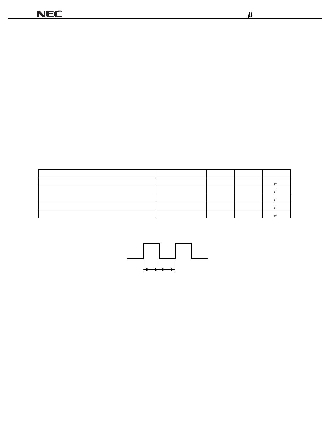
Figure 4-1. LPS Waveform when Connected to Isolation Barrier
tLPSH
tLPSL
Data Sheet S14452EJ1V0DS00
21
Share Link: 