MTD800 Ver la hoja de datos (PDF) - Myson Century Inc
Número de pieza
componentes Descripción
Lista de partido
MTD800 Datasheet PDF : 42 Pages
| |||
MYSON
TECHNOLOGY
MTD 800
(Preliminary)
3.0 FUNCTIONAL DESCRIPTION
3.1 PCI Bus Operation
The peripheral component interconnect (PCI) is a high-speed backplane in modern PC. The MTD800 uses
the PCI bus to communicate with the host CPU and main memory to achieve high performance network com-
putation. The MTD800 is directly compatible with revision 2.2 of the PCI Local Bus Specification and supports
a subset of the PCI bus transactions. It contains I/O read/write, Memory read/write and Configuration read/
write operations. Besides that, all kinds of termination cycle are also supported. The MTD800 is acting as a
PCI bus target when handshaking with the host, while operating as a PCI bus initiator when communicating
with the host memory.
3.2 DMA Transmit Function
The DMA Transmit Function is responsible for fetching data from the host’s memory into the on-chip transmit
FIFO, and then signalling MAC transmit interface to relay the transmitted data onto the network if the fullness
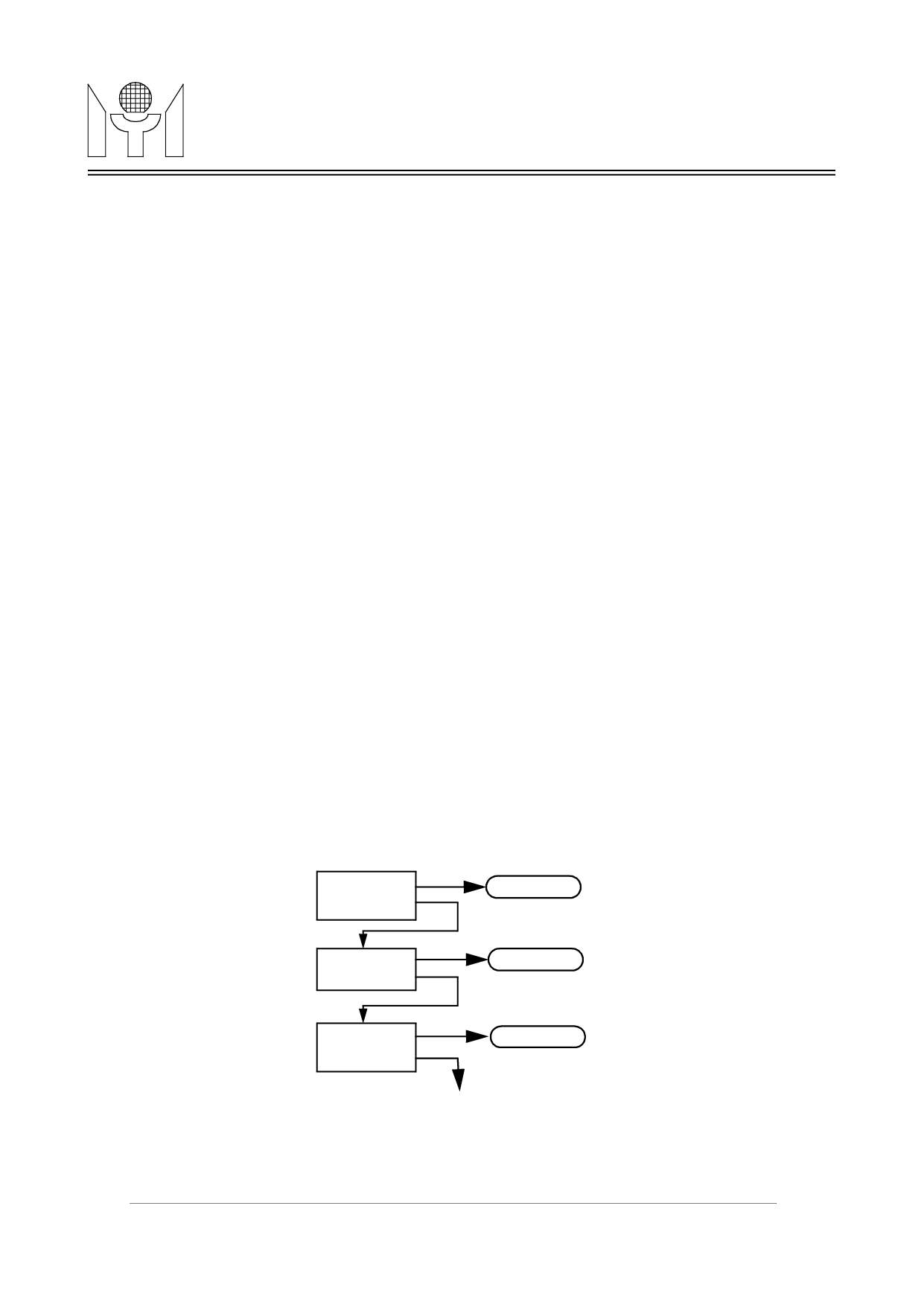
of FIFO reaches the predefined threshold. The structure for the data to be transmitted is described in a format
of chained link list(see figure 3.1). Descriptors that reside in the host memory act as pointers to these transmit
buffers. The transmit descriptor format is shown as figure 3.2. It consists of four long words. The first two
words contain the transmit frame status, frame length and the descriptor ownership information. The last two
words are the address pointers for the current data buffer and the next descriptor. The bit field definition of the
descriptor words are given in table 3.1 and table 3.2 respectively. Note that the transmit buffer address are not
necessary to be in alignment of longword while the descriptors address should be longword aligned. The own-
ership of buffer is indicated in the “own” bit of the first descriptor. When driver has completed the preparation
of being transmitted packet, it sets the “own” bit to represent the buffer that belongs to the MTD800, and
demands MTD800 to fetch the buffer and the associated descriptor. After the packet has been transmitted
onto the network, the MTD800 clears the “own” bit and issues an interrupt to notify the driver that the buffer
can be reused. Meanwhile, the driver is able to acquire the transmit status by reading the “TSW” in the first
descriptor. The MTD800 also has an advanced feature to enhance the transmit performance by “closing” the
first descriptor early once the packet has been transferred into the FIFO completely.
Descriptor 0
Buffer 0
Descriptor 1
Buffer 1
Descriptor 2
Buffer 2
point to
next descriptor
Figure 3.1 Descriptor chained structure
6/42
MTD800 Revision 0.0 07/20/1999
Share Link: 